Efficient industrial boiler pre-combustion chamber

A technology for industrial boilers and pre-combustion chambers, applied in combustion chambers, combustion methods, combustion equipment and other directions, can solve the problems of poor heat recovery effect of pre-combustion chambers, inability to absorb heat energy of pre-combustion chambers, and reduced pre-combustion work efficiency, etc. Achieve high heat exchange efficiency, high work efficiency, and reduce heat exchange.

Inactive Publication Date: 2021-03-26
上海窍妙科技有限公司
View PDF0 Cites 1 Cited by
  • Summary
  • Abstract
  • Description
  • Claims
  • Application Information

AI Technical Summary

Problems solved by technology

[0002] In our daily life, coal-fired industrial filtration is the leading product in our country, and most of them have large capacity. The combustion chamber of general industrial boilers has a large capacity and can accommodate more dyes. At the same time, it requires more preheating of coal-fired High, the pre-combustion chamber of general industrial boilers can carry out combustion-supporting in advance and blow the dye into the combustion chamber of industrial boilers through secondary air blowing. The heat recovery effect of the pre-combustion chamber of general industrial boilers is not good, and the water-cooled pipe is working during preheating. At the beginning, the pre-combustion chamber will be too low, resulting in a decrease in the pre-combustion work efficiency, and the heat energy inside the pre-combustion chamber cannot be absorbed well and efficiently during the subsequent water-cooling process. A high-efficiency industrial boiler described in the present invention Pre-combustion chamber, which can solve the above problems

Method used


Image

  • Efficient industrial boiler pre-combustion chamber
  • Efficient industrial boiler pre-combustion chamber
  • Efficient industrial boiler pre-combustion chamber

Examples


Embodiment Construction

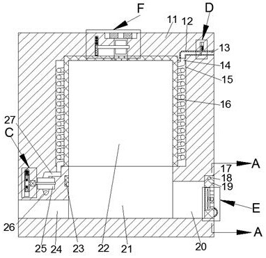
[0024] Combine below Figure 1-9 The present invention is described in detail, and for convenience of description, the orientations mentioned below are now stipulated as follows: figure 1 The up, down, left, right, front and back directions of the projection relationship itself are the same.

[0025]A high-efficiency industrial boiler pre-combustion chamber according to the present invention includes a pre-combustion chamber main body 11, a pre-combustion chamber 21 is provided inside the pre-combustion chamber main body 11, and a heat exhausting chamber is connected to the upper side of the pre-combustion chamber 21 cavity 22, the inner wall and upper wall of the heat discharge cavity 22 are fixed with a heat exchange plate 16 made of heat transfer material, and the outer side of the heat discharge cavity 22 is provided with a circular water-cooled heat exchange cavity 15, the water A threaded water cooling pipe 14 is provided in the cold and heat exchange chamber 15, and a ...


PUM


Abstract

The invention discloses an efficient industrial boiler pre-combustion chamber which comprises a pre-combustion chamber body. A pre-combustion cavity is formed in the pre-combustion chamber body, the upper side of the pre-combustion cavity communicates with a heat removal cavity, heat exchange plates made of heat transfer materials are fixedly arranged on the inner wall and the upper wall of the heat removal cavity, an annular water-cooling heat exchange cavity is formed in the outer side of the heat removal cavity, and a spiral water-colling pipeline is arranged in the water-cooling heat exchange cavity. The rotating speed of a water pump is controlled and reduced at the initial stage of ignition of the pre-combustion chamber through temperature detection, so that the flowing of cooling water in the water-cooling pipeline is further slowed down, the heat exchange in the pre-combustion chamber is reduced, and the combustion efficiency of fuel is improved; and then, through temperature detection, when the temperature rises, flowing of cooling water is accelerated, heat energy recovery is improved, meanwhile, the area of a waste gas exhaust port is controlled through the exhaust amount of waste gas, the effect of controlling the exhaust rate of the waste gas is achieved, the heat exchange efficiency in the pre-combustion chamber is further improved, and the overall working efficiency of the pre-combustion chamber is improved.

Description

technical field [0001] The invention relates to the field of industrial furnaces, in particular to a high-efficiency industrial boiler pre-combustion chamber. Background technique [0002] In our daily life, coal-fired industrial filtration is the leading product in our country, and most of them have large capacity. The combustion chamber of general industrial boilers has a large capacity and can accommodate more dyes. At the same time, it requires more preheating of coal-fired High, the pre-combustion chamber of general industrial boilers can carry out combustion-supporting in advance and blow the dye into the combustion chamber of industrial boilers through secondary air blowing. The heat recovery effect of the pre-combustion chamber of general industrial boilers is not good, and the water-cooled pipe is working during preheating. At the beginning, the pre-combustion chamber will be too low, resulting in a decrease in the pre-combustion work efficiency, and the heat energy...

Claims


Application Information

Patent Timeline
Patent Type & Authority Applications(China)
IPC IPC(8): F23B10/02F23M5/08F23J15/02
CPCF23B10/02F23J15/025F23M5/08
Inventor 王绪昌
Owner 上海窍妙科技有限公司
Why Eureka
Try Eureka