Filling station cold energy utilization device

A technology of cold energy and cold box, which is applied in the field of cold energy utilization devices in filling stations, can solve problems such as waste of cold energy and exhaust gas discharge, and achieve the effect of eliminating safety problems, ensuring safety, and good recycling effect

Pending Publication Date: 2021-03-26
珠海森铂低温能源装备有限公司
View PDF0 Cites 0 Cited by
  • Summary
  • Abstract
  • Description
  • Claims
  • Application Information

AI Technical Summary

Problems solved by technology

[0005] In the traditional market, industrial gas filling not only wastes cooling capacity, but also emits exhaust gas;

Method used


Image

  • Filling station cold energy utilization device

Examples


Embodiment Construction

[0032] In order to make the object, technical solution and advantages of the present invention clearer, the present invention will be further described in detail below in conjunction with the accompanying drawings and embodiments. It should be understood that the specific embodiments described here are only used to explain the present invention, not to limit the present invention.

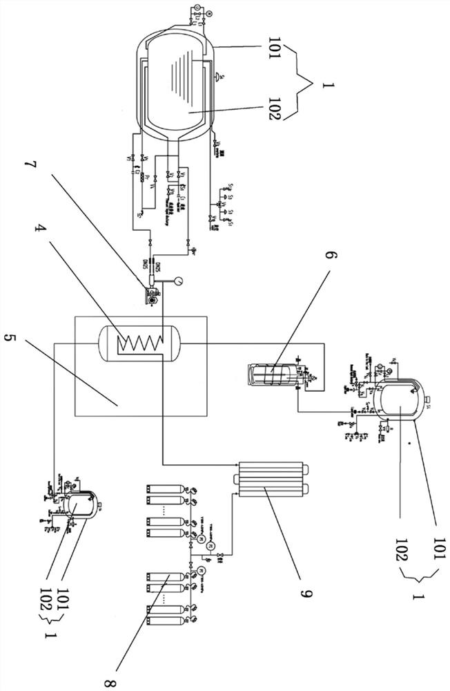
[0033] A cold energy utilization device for a filling station, characterized in that the utilization device includes three low-temperature liquid storage tanks, a low-temperature filling drag pump, a heat exchanger, a cold box, a cryogenic bottle, a vaporizer, and a gas cylinder group;

[0034] The cryogenic liquid storage tank is composed of an outer tank and an inner tank, the inner tank is arranged in the outer tank, and the middle of the two is a multi-layer winding high-vacuum interlayer;

[0035] The cryogenic liquid storage tank is also provided with a liquid discharge pipe and a liquid inle...


PUM


Abstract

The invention discloses a filling station cold energy utilization device. The filling station cold energy utilization device is characterized in that the utilization device comprises three low-temperature liquid storage tanks, a low-temperature filling trailer pump, a heat exchanger, a cold box, a low-temperature bottle, a vaporizer and a gas bottle group. The heat exchanger is arranged, cold energy charged in a normal-temperature steel bottle is collected through the heat exchanger, and cold energy is saved; and the cold energy charged in the normal-temperature steel bottle is used for condensing waste gas charged in the low-temperature bottle by utilizing the heat exchanger, so that the waste gas is prevented from being discharged and enters the low-temperature storage tanks to be storedafter being condensed, the waste gas is repeatedly used during subsequent charging, waste is turned into wealth, and the device is more environment-friendly.

Description

【Technical field】 [0001] The invention relates to the field of energy, in particular to a cold energy utilization device for a filling station. 【Background technique】 [0002] At present, the filling of industrial gases in the traditional market is divided into filling of normal temperature steel cylinders and low temperature steel cylinders. [0003] The filling of the normal temperature steel cylinder is that the low temperature storage tank is connected to the bottle filling pump and then directly vaporized and loaded into the normal temperature gas cylinder after being pressurized. During the filling process, the cooling capacity of the cryogenic liquid is directly transferred from the vaporizer to the surrounding air, which is equivalent to the direct waste of cooling capacity; [0004] Cryogenic steel cylinders are directly connected to cryogenic storage tanks for self-flow filling. During the filling process, due to the heat transfer of the low-temperature steel cyl...

Claims


Application Information

Patent Timeline
IPC IPC(8): F17C6/00F17C9/04F17C13/00F17C13/02F17C3/08
CPCF17C3/08F17C6/00F17C9/04F17C13/00F17C13/02F17C13/021F17C13/025F17C13/026F17C2227/03
Inventor 陈强何中银刘贤玖贾庆广
Owner 珠海森铂低温能源装备有限公司
Why Eureka
Try Eureka