Steam turbine rotor blade fitting machining method
A steam turbine rotor and processing method technology, applied to metal processing equipment, metal processing machinery parts, manufacturing tools, etc., can solve the problems of large equipment constraints, high processing costs, low efficiency, etc., achieve low processing accuracy, save production costs, The effect of improving economic efficiency
- Summary
- Abstract
- Description
- Claims
- Application Information
AI Technical Summary
Problems solved by technology
Method used
Image
Examples
specific Embodiment approach 1
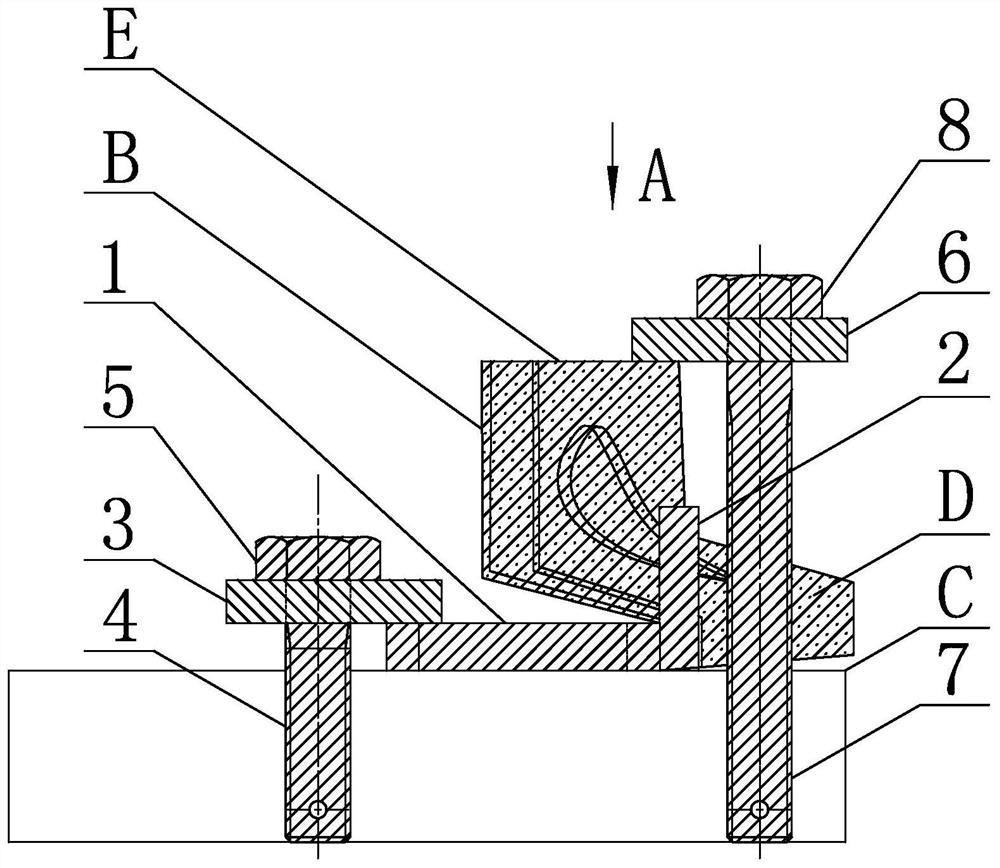
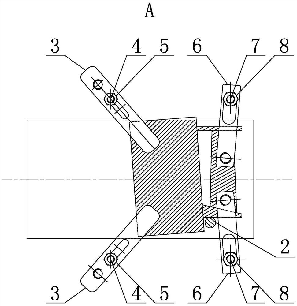
[0057] Specific implementation mode one: combine Figure 1 to Figure 3 Describe this embodiment, a steam turbine rotor blade brush matching processing method in this embodiment, the method is realized by the following steps,
[0058] Step 1. Alignment and clamping of the first blade B:
[0059] Step 11. Placement of the first blade B:
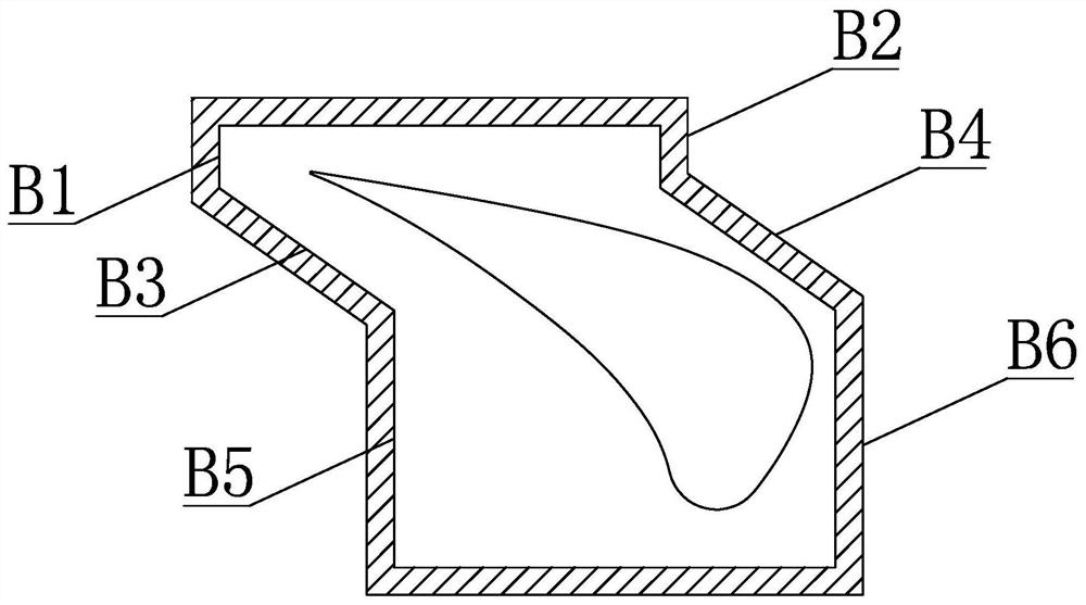
[0060] First place the square iron 1 on the upper end surface of the three-axis linkage CNC machine tool table C according to the complementary twist angle of the blade B to be processed. The square iron 1 is located between the two T-shaped slots of the CNC machine tool table C to ensure that it is processed When the blade B leans against the square iron 1, the first surface to be processed B1, the second surface to be processed B2, the fifth surface to be processed B5 and the sixth surface to be processed B6 of the processed blade B are perpendicular to the X axis of the machine tool;
[0061] Step 12. Determination of the reference plane D...
specific Embodiment approach 2
[0076] Specific implementation mode two: combination figure 1 and figure 2 Describe this embodiment, each set of first clamping parts described in step 14 of this embodiment includes a first pressure plate 3, a first bolt 4 and a first nut 5, and when clamping a square iron 1, the The first pressure plate 3 is horizontally placed above the square iron 1, one end of the first pressure plate 3 is lapped on the upper end surface of the square iron 1, and the lower end of the first bolt 4 is vertically inserted on the CNC machine tool workbench from top to bottom In the T-shaped groove of C, the upper end of the first bolt 4 passes through the strip-shaped through hole of the first pressure plate 3 from bottom to top in the vertical direction and is screwed with the first nut 5, and the first pressure plate 3 is connected by the first nut 5 The square iron 1 is compressed on the workbench C of the CNC machine tool. With such an arrangement, when processing the blades, there is ...
specific Embodiment approach 3
[0077] Specific implementation mode three: combination figure 1 and figure 2 To illustrate this embodiment, each set of second clamping parts described in step 15 of this embodiment includes a second pressure plate 6, a second bolt 7 and a second nut 9, and when the blade B is clamped, the second The second pressure plate 6 is horizontally placed above the blade B, one end of the second pressure plate 6 is lapped on the non-processing surface E of the blade B, and the lower end of the second bolt 7 is vertically inserted on the CNC machine workbench C from top to bottom In the T-shaped slot of the second bolt 7, the upper end of the second bolt 7 passes through the strip-shaped through hole of the second pressure plate 6 from bottom to top in the vertical direction and is screwed with the second nut 9, and the second pressure plate 6 connects the blades through the second nut 9. B is compressed on the workbench C of the CNC machine tool. With such an arrangement, when proce...
PUM
 Abstract
Description
Claims
Application Information
 - R&D
- Intellectual Property
- Life Sciences
- Materials
- Tech Scout
- Unparalleled Data Quality
- Higher Quality Content
- 60% Fewer Hallucinations
Browse by: Latest US Patents, China's latest patents, Technical Efficacy Thesaurus, Application Domain, Technology Topic, Popular Technical Reports.
© 2025 PatSnap. All rights reserved.Legal|Privacy policy|Modern Slavery Act Transparency Statement|Sitemap|About US| Contact US: help@patsnap.com


