
Cast hollow blade wall thickness control method based on mold core self-adaptive positioning

A hollow blade and control method technology, applied in cores, casting molding equipment, casting molds, etc., can solve the problems of inability to meet the requirements of aero-engine test and assessment, long cycle, large capital investment, etc., to shorten the mold iteration cycle, improve Qualification rate, the effect of reducing production cost

Active Publication Date: 2021-03-26
AVIC BEIJING INST OF AERONAUTICAL MATERIALS
View PDF5 Cites 3 Cited by
  • Summary
  • Abstract
  • Description
  • Claims
  • Application Information

AI Technical Summary

Problems solved by technology

In order to improve the wall thickness and dimensional accuracy of blade castings, it is usually necessary to put into production multiple sets of cores and wax molds, and after multiple rounds of iterative verification, the cycle is long and the capital investment is large, which cannot meet the current short-term test assessment for aero-engines Require

Method used


Image

  • Cast hollow blade wall thickness control method based on mold core self-adaptive positioning
  • Cast hollow blade wall thickness control method based on mold core self-adaptive positioning
  • Cast hollow blade wall thickness control method based on mold core self-adaptive positioning

Examples


Embodiment 1

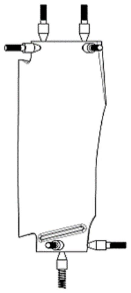
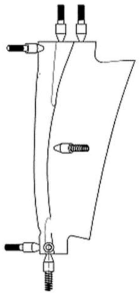
[0028] Taking a typical turbine guide vane as the verification object, the distribution of 6 positioning points and 2 pressing points selected to maintain the posture of the ceramic core in the wax mold compression mold is shown in figure 1 and figure 2 .

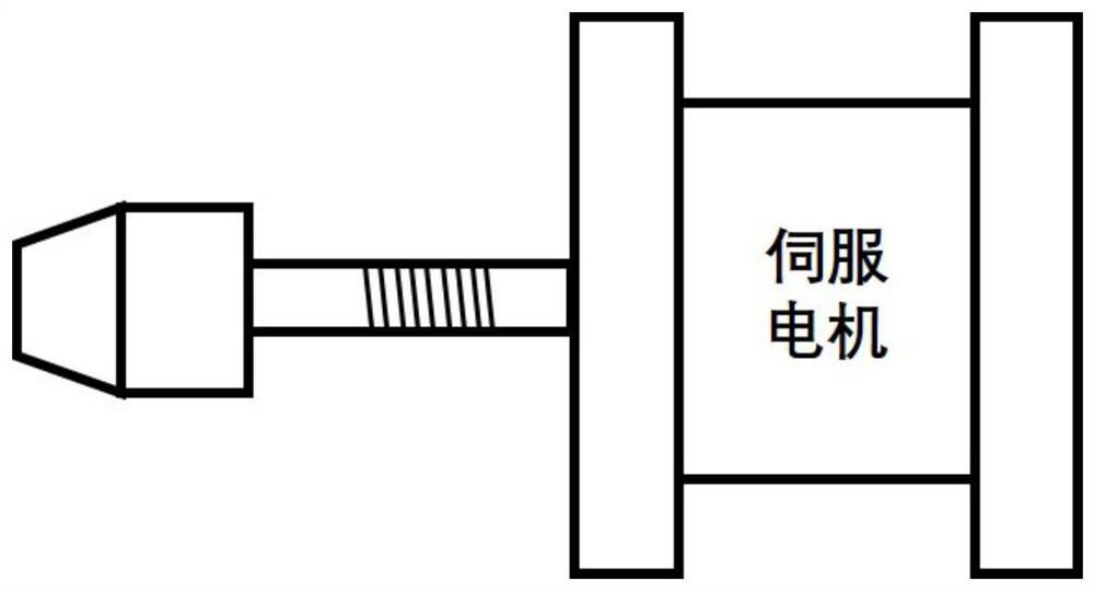
[0029] At the positioning point, there is a positioning boss that is driven by a motor to rotate and adjust the height. The design structure is shown in image 3 , including the front section, middle section, rear section and pins with external threads. Among them, the radius of the upper bottom of the front section is 2mm, the radius of the lower bottom is 4mm, the height is the same as the local theoretical wall thickness at the positioning point, and the circumferential edges of the upper bottom surface of the circular table are rounded; the middle section of the boss is cylindrical, the bottom surface radius is 4mm, and the height is 10mm; The back section of the boss is cylindrical, the radius of the bottom surface ...

Embodiment 2

[0038] Taking a typical turbine working blade as the verification object, the distribution positions of the 6 positioning points and 2 pressing points selected to maintain the posture of the ceramic core in the wax mold are shown in Figure 8 and Figure 9 .

[0039] At the positioning point, there is a positioning boss that is driven by a motor to rotate and adjust the height. The design structure is shown in image 3 , including the front section, middle section, rear section and pins with external threads. Among them, the radius of the upper bottom of the front section is 1mm, the radius of the lower bottom is 2mm, the height is the same as the local theoretical wall thickness at the positioning point, and the circumferential edges of the upper bottom of the circular platform are rounded; the middle section of the convex platform is cylindrical, the radius of the bottom surface is 2mm, and the height is 3mm; The back section of the boss is cylindrical, the radius of the b...


PUM

PropertyMeasurementUnit
heightaaaaaaaaaa
heightaaaaaaaaaa
radiusaaaaaaaaaa

Abstract

The invention belongs to the field of casting of high-temperature alloy hollow turbine blades, and relates to a method for self-adaptive positioning of a ceramic mold core in a wax mold pressing mold.By optimizing the structural design scheme of a mold core mold and the wax mold pressing mold, a ceramic mold core formed through sintering is placed in the wax mold pressing mold, and the pose of the ceramic mold core in an appearance mold is controlled through six height-adjustable positioning bosses embedded in a loose piece of the wax mold pressing mold; and it is guaranteed that the mold core and the positioning bosses are in an attached state through 1-3 elastic press-fit devices with a limiting function which are embedded in the loose piece of the wax mold pressing mold. The method issimple and easy to implement, effectively reduces wall thickness out-of-tolerance scrapping caused by core shift of a blade, improves the wall thickness size precision and consistency of a cast part,greatly improves the product percent of pass, reduces economic losses, shortens the product development period and reduces the mold iteration cost.

Description

technical field [0001] The invention belongs to the technical field of investment precision casting superalloys, and in particular relates to a method for controlling the wall thickness of a hollow blade in which a ceramic core is self-adaptively positioned in a wax mold pressing mold. Background technique [0002] Turbine blades are important hot-end components of aero-engines. They have been in extremely harsh working environments for a long time, and their reliability is crucial to the stability and service life of aero-engines. The increase of turbine inlet temperature is crucial to the improvement of engine working efficiency. Therefore, advanced aero-engines design turbine blades as hollow structures, and the mainstream preparation process is investment casting. [0003] In order to pursue excellent aerodynamic performance, the contour of the turbine blade is usually designed as a three-dimensional composite curved and twisted shape, and the wall thickness is relativel...

Claims


Application Information

Patent Timeline
Patent Type & Authority Applications(China)
IPC IPC(8): B22C9/04B22C9/10B22C9/22
CPCB22C9/04B22C9/22B22C9/108Y02T50/60
Inventor 杨泽南于俊杰谢强张春雷王祯张强刘强军
Owner AVIC BEIJING INST OF AERONAUTICAL MATERIALS
Learn More