High-rigidity small-sized steel row straightening machine with movable operation side rack

A row straightening machine and operation side technology, which is applied in the field of small steel row leveling machines with mobile racks on the operation side and high rigidity, can solve the problems of low technical and economic advantages, high maintenance requirements, and unsuitable equipment selection requirements And other issues

Pending Publication Date: 2021-03-26
HUATIAN ENG & TECH CORP MCC
View PDF0 Cites 1 Cited by
  • Summary
  • Abstract
  • Description
  • Claims
  • Application Information

AI Technical Summary

Problems solved by technology

However, the hydraulic cylinder used for the vertical movement of the upper straightening roller has high requirements, the hydraulic system is complicated, and the maintenance requirements are high. Therefore, the overall technical and economic advantages are not obvious, and the defects have a great impact on the application of small steel row levelers.
Due to the compact structure of the small-sized steel straightening machine in a row, the distance between the straightening rollers is small, and it is impossible to arrange hydraulic cylinders at the lower parts of the two sides of the straightening machine frame; Requirements for equipment selection suitable for small steel row straightening machines

Method used


Image

  • High-rigidity small-sized steel row straightening machine with movable operation side rack
  • High-rigidity small-sized steel row straightening machine with movable operation side rack
  • High-rigidity small-sized steel row straightening machine with movable operation side rack

Examples


Embodiment Construction

[0049] The present invention will be further described below in conjunction with the accompanying drawings.

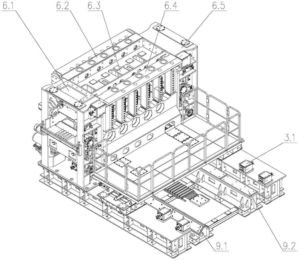
[0050] like Figure 1 to Figure 19 As shown, a mobile high-rigidity small-sized steel row straightening machine with an operation side frame of the present invention includes a fixed base 1, a comprehensive base 3, a longitudinal moving track 9, a high-rigidity combined frame 6, and an automatic locking type upper straightening machine. Roll assembly 5, automatic locking type lower straightening roll assembly 4, clutch type pressing device 7, automatic roll changing device 2 and transmission system 8.

[0051] The fixed base 1 is arranged under the transmission side frame 6.2 of the combined frame 6, between the front frame 6.1 and the rear frame 6.5, is fixed on the civil foundation, and carries the combined frame 6 together with the integrated base 3.

[0052] The integrated base 6 is arranged vertically to the rolling line, and is located outside and parallel to th...


PUM


Abstract

The invention discloses a high-rigidity small-sized steel row straightening machine with a movable operation side rack. The high-rigidity small-sized steel row straightening machine comprises a high-rigidity combined rack, an automatic locking type upper straightening roller, an automatic locking type lower straightening roller, a clutch type pressing device, an automatic roller replacing device,a longitudinal moving rail, a base and a transmission system, wherein bearing supporting systems at the two ends of the automatic locking type lower straightening roller are installed in fixed installation holes formed in the lower portion of the high-rigidity combined rack in advance; bearing seats at the two ends of the automatic locking type upper straightening roller are installed in sliding grooves of upper window structures of racks on the two sides in the high-rigidity combined rack; the clutch type pressing device is mounted at the top of a pressing device rack in the high-rigidity combined rack; screws on the two sides of the clutch type pressing device are connected with bearing seats on the two sides of the automatic locking type upper straightening roller respectively; and theautomatic roller replacing device is installed in the high-rigidity combined rack, an automatic roller replacing vehicle is left in the machine during straightening operation, and an upper roller setbracket retreats from the machine. The high-rigidity small-sized steel row straightening machine has the characteristics of compact structure, good economy, high automation degree and the like.

Description

technical field [0001] The invention relates to a row straightening machine, in particular to a mobile high rigidity small steel row straightening machine of an operation side frame. Background technique [0002] Straightening of small steel usually adopts cantilever straightening machine; it is suitable for off-line straightening process. The frame of the cantilever straightener is a welded integral frame, the straightening roller is installed on the cantilever shaft end of the straightening machine, the bearing on the operating side of the straightening machine is more stressed than the bearing on the transmission side, and the deflection of the cantilever shaft end is large. Due to the cantilever arrangement of the straightening rolls, the width of the roll surface is narrow, it is difficult to arrange multiple passes, and it is impossible to straighten multiple sections at the same time, and the capacity matching of the rolled section steel is limited. [0003] Use stra...

Claims


Application Information

Patent Timeline
IPC IPC(8): B21D3/05B21D37/10B21D37/14
CPCB21D3/05B21D37/10B21D37/14
Inventor 卫卫方实年石海军徐志坤董岱陈建
Owner HUATIAN ENG & TECH CORP MCC
Why Eureka
Try Eureka