Airflow fiber laying and covering device

A fiber and laying technology, which is applied in the field of air-flow laying fiber device, can solve the problems of fiber agglomeration, agglomeration, poor coating and hanging performance, etc.

Active Publication Date: 2021-03-19
INNER MONGOLIA UNIV OF TECH
View PDF4 Cites 1 Cited by
  • Summary
  • Abstract
  • Description
  • Claims
  • Application Information

AI Technical Summary

Problems solved by technology

However, a bottleneck problem has been encountered in the process of preparing the shell. When fibers with a large aspect ratio are blended into the coating and added to the shell, as the fiber blending ratio increases, the viscosity of the coating increases, the suspending property decreases, and the coating performance deteriorates. , the fibers will agglomerate or agglomerate, which will eventually lead to a decrease in the strength of the shell
use as figure 1 In the initial laying of the fiber device shown, as the laying time prolongs, a small amount of fibers will fall on the wall of the four-sided platform at the lower part of the device. Periodic movement, when the laying time exceeds 20s, affected by the wall effect, the fibers near the wall will move parallel to the wall and gather at the junction between the four-sided platform wall and the four-sided living wall, even if the airflow pressure is increased , the fibers remain still and do not move in suspension, and the airflow velocity at the junction of the walls is low or even the airflow cannot reach it, resulting in a dead angle of airflow, resulting in the deposition of a large number of fibers, resulting in a low proportion of fibers covering the surface of the shell

Method used


Image

  • Airflow fiber laying and covering device
  • Airflow fiber laying and covering device
  • Airflow fiber laying and covering device

Examples


Embodiment Construction

[0071] 1. Analysis of the mathematical model of the prior art air-laid fiber device

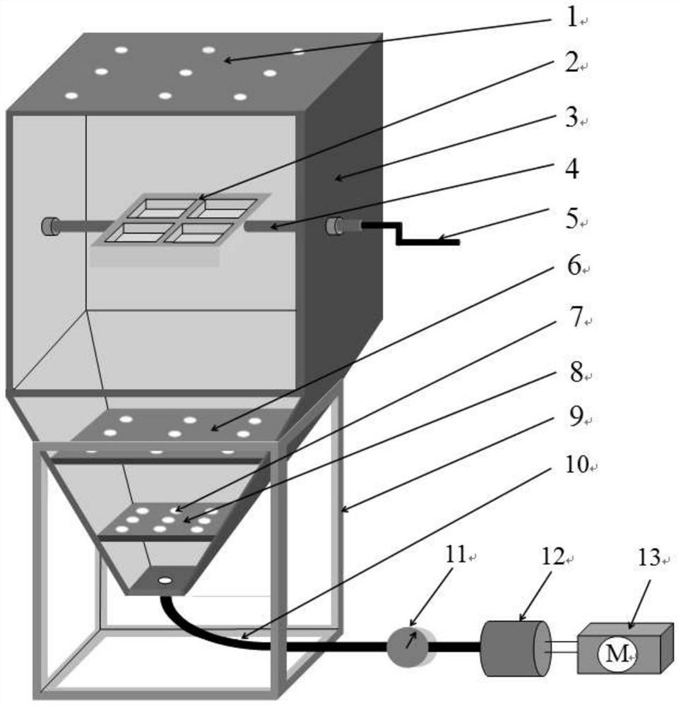
[0072] For the prior art ( figure 1 ) shows the analysis of the air-flow fiber-laying device, it is found that the fiber-laying time is prolonged, and the fiber will sink to each wall of the device, and no longer do the suspension movement. The occurrence of this phenomenon is directly related to the air distribution, fiber stress and device structure. The force of the fiber in the airflow is more complicated, including the force of the flow field on the fiber, the gravity of the fiber, the force between the fibers, etc., among which the force of the flow field on the fiber has the greatest influence on the movement state of the fiber. In order to prolong the suspension time of the fiber in the device, increase the probability of the fiber touching the surface of the shell, and increase the percentage of the fiber covering the shell, it is necessary to analyze the movement state and distribu...


PUM

PropertyMeasurementUnit
Diameteraaaaaaaaaa
Diameteraaaaaaaaaa
Diameteraaaaaaaaaa

Abstract

The invention discloses an airflow fiber laying and covering device which comprises a transition area, a material distribution and flow expansion area, a fiber laying and covering area and a flow guide contraction area which are coaxial. Gas enters from the gas inlet end of the transition area, sequentially penetrates through the material distribution and flow expansion area, the fiber laying andcovering area and the flow guide contraction area and is exhausted from the gas outlet end of the flow guide contraction area; a material distribution pore plate coaxial with the transition area is arranged in the transition area; a gas guide pore plate coaxial with the material distribution and flow expansion area is arranged in the material distribution and flow expansion area; a gas outlet endof the flow guide contraction area is provided with a gas exhaust pore plate coaxial with the flow guide contraction area; and a sample clamp is arranged in the fiber laying and covering area. The fiber laying and covering device combining a cylinder and a circular truncated cone can avoid airflow dead angles caused by low airflow speed at the wall surface combination position and even incapability of airflow to reach at the wall surface combination position, so that deposition of a large amount of fibers is avoided, and the fiber laying and covering proportion is increased. The pore opening position and the pore opening rate of the pore plate are designed, so that the radial airflow distribution is more uniform, and the fiber distribution uniformity is improved.

Description

technical field [0001] The invention relates to the technical field of casting investment devices. Specifically, it is an air-laid fiber device. Background technique [0002] The applicant has used single fibers and hybrid fibers as reinforcing media, and by blending them into coatings and adding silica sol mold shells, the normal temperature strength of the mold shells has been improved to varying degrees, and its comprehensive performance has been improved (CN108213344A). However, a bottleneck problem has been encountered in the process of preparing the shell. When fibers with a large aspect ratio are blended into the coating and added to the shell, as the fiber blending ratio increases, the viscosity of the coating increases, the suspending property decreases, and the coating performance deteriorates. , the fibers will agglomerate or agglomerate, which will eventually lead to a decrease in the strength of the shell. use as figure 1 In the initial laying of the fiber de...

Claims


Application Information

Patent Timeline
IPC IPC(8): D04H1/732
CPCD04H1/732
Inventor 李艳芬路焱吕凯张翔
Owner INNER MONGOLIA UNIV OF TECH
Why Eureka
Try Eureka