Separation chip, separation device and separation method

A separation chip and filter membrane technology, applied in the biological field, can solve the problems of easy clogging, long time consumption, and frequent replacement of filter membranes, and achieve the effects of reducing the frequency of replacing filter membranes, improving separation efficiency, and reducing the probability of damage

Pending Publication Date: 2021-03-19
SHENZHEN TECH UNIV
View PDF0 Cites 0 Cited by
  • Summary
  • Abstract
  • Description
  • Claims
  • Application Information

AI Technical Summary

Problems solved by technology

[0003] However, the use of ultracentrifugation to separate extracellular vesicles is costly and time-consuming, and the large centrifugal force may affect the integrity of extracellular vesicles; the polymer precipitation method requires the introduction of polymers, which is not conducive to downstream proteins Omics detection and application and detection of gene amplification; the cost of isolation of extracellular vesicles by immunoprecipitation is high, and only extracellular vesicles of specific components can be isolated; the difference in the size exclusion method of separating exosome samples will affect the Collection time of exovesicles, poor reproducibility
[0004] In addition, there is also a filter membrane separation method that uses a filter membrane to separate samples. However, during the separation process of the traditional filter membrane separation method, the filter membrane is easily blocked, the use efficiency of the filter membrane is low, the replacement is frequent, and the sample separation is not continuous. damage to the filter membrane

Method used


Image

  • Separation chip, separation device and separation method
  • Separation chip, separation device and separation method
  • Separation chip, separation device and separation method

Examples


Embodiment Construction

[0047] The technical solutions of the present invention will be described below in combination with preferred implementation modes and examples of the present invention. It should be noted that when an element is described as being "connected" to another element, it can be directly connected to the other element or there may be intervening elements at the same time. When an element is described as being "disposed on" another element, it can be directly on the other element or intervening elements may also be present. Unless otherwise defined, all technical and scientific terms used herein have the same meaning as commonly understood by one of ordinary skill in the technical field of the invention. The names of elements or devices used in the description of the present invention are only for the purpose of describing specific embodiments, and are not intended to limit the present invention.

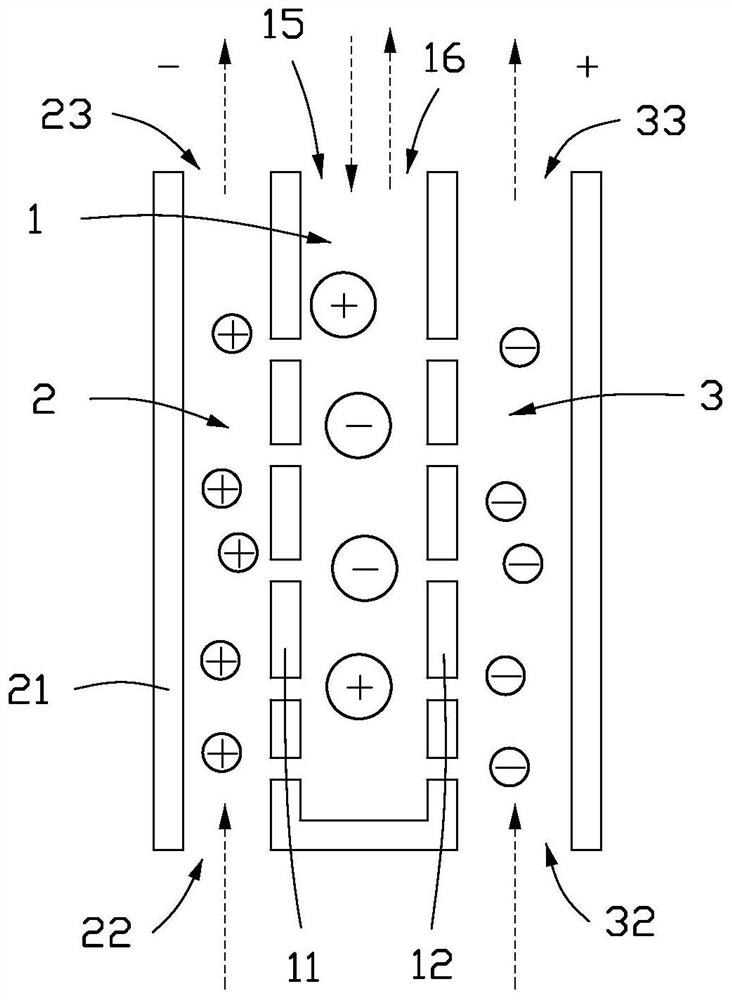
[0048] see figure 1 , the present invention firstly provides a separation chip 100, ...


PUM

PropertyMeasurementUnit
pore sizeaaaaaaaaaa

Abstract

The invention provides a separation chip. The separation chip comprises a sample pool, a first chamber, a second chamber and power supplies. The sample pool comprises first filter membranes and secondfilter membranes, and the first filter membranes are opposite to the second filter membranes. The first chamber is connected to the sample pool through the first filter membranes, the first chamber comprises a first outer wall, the first outer wall is arranged on one side, far away from the second filter membranes, of the first filter membranes, and the first chamber is connected to the outside.The second chamber is connected to the sample pool through the second filter membranes, the second chamber comprises a second outer wall, the second outer wall is arranged on one side, away from the first filter membranes, of the second filter membranes, and the second chamber is connected to the outside. The power supplies are used for providing an electric field applied between the first outer wall and the second outer wall. The separation chip provided by the invention can realize continuous separation, the separation efficiency is improved, and the cost is reduced. The invention also provides a separation device and a separation method for separating target particles in a to-be-detected sample.

Description

technical field [0001] The invention relates to the field of biotechnology, in particular to a separation chip, a separation device and a separation method for separating target particles in a sample to be detected. Background technique [0002] Existing extracellular vesicle isolation methods mainly include methods such as ultracentrifugation, polymer precipitation, immunoprecipitation, and size exclusion. [0003] However, the use of ultracentrifugation to separate extracellular vesicles is costly and time-consuming, and the large centrifugal force may affect the integrity of extracellular vesicles; the polymer precipitation method requires the introduction of polymers, which is not conducive to downstream proteins Omics detection and application and detection of gene amplification; the cost of isolation of extracellular vesicles by immunoprecipitation is high, and only extracellular vesicles of specific components can be isolated; the difference in the size exclusion meth...

Claims


Application Information

Patent Timeline
Patent Type & Authority Applications(China)
IPC IPC(8): C12M1/12C12M1/42C12M1/00
CPCC12M23/34C12M47/04
Inventor 邓载安吴江红胡俊青
Owner SHENZHEN TECH UNIV
Why Eureka
Try Eureka