
Novel plate stamping mechanical equipment convenient for stamping

A technology of mechanical equipment and new type of sheet metal, applied in the field of new sheet metal stamping machinery and equipment, can solve problems such as limited hand-held area, personal injury to workers, and danger, and achieve the effect of improving product quality, reasonable structure, and increasing accuracy

Inactive Publication Date: 2021-03-19
德清县杰创机械有限公司
View PDF0 Cites 3 Cited by
  • Summary
  • Abstract
  • Description
  • Claims
  • Application Information

AI Technical Summary

Problems solved by technology

[0003] In the prior art, the stamping production of small products is mostly done by manual loading and unloading, especially when performing punching operations such as small strip brackets or thin plates, workers need to hold the stamped sheet and put it into the stamping die. Due to the small size of the product, the hand-held area Limited, there is danger in the stamping process, which will cause great personal injury to workers, so we disclose a new type of sheet metal stamping machinery and equipment that is convenient for stamping to meet people's needs

Method used


Image

  • Novel plate stamping mechanical equipment convenient for stamping
  • Novel plate stamping mechanical equipment convenient for stamping
  • Novel plate stamping mechanical equipment convenient for stamping

Examples


Embodiment

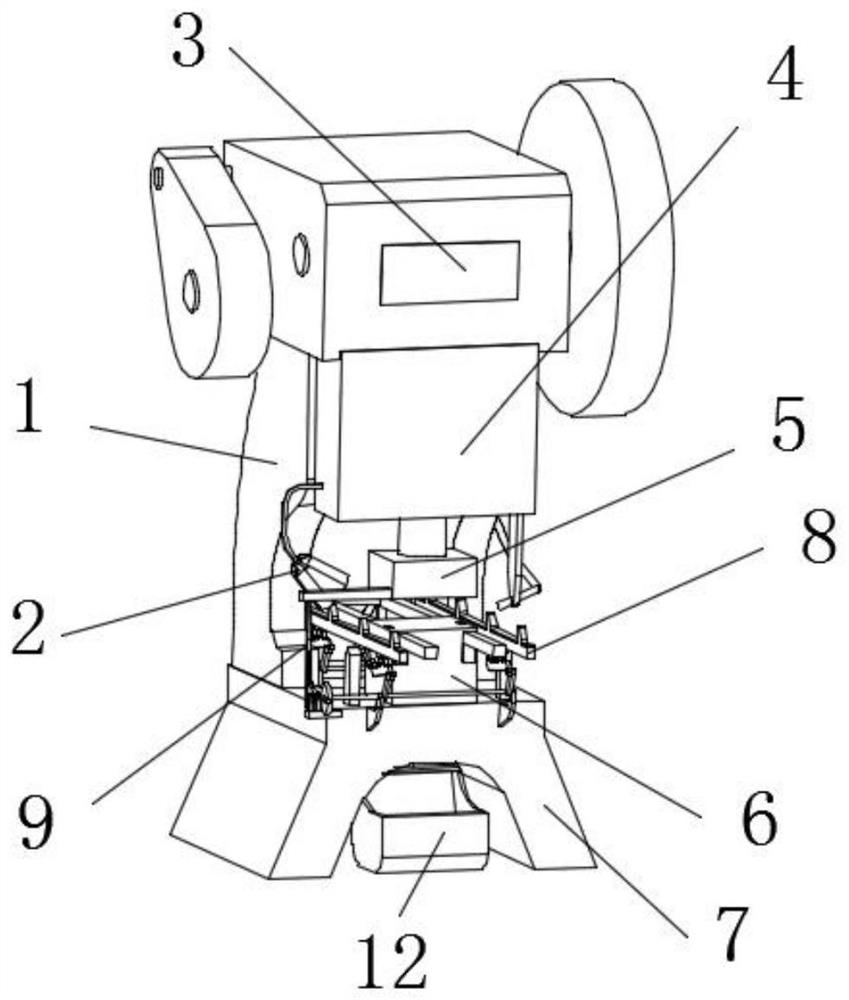
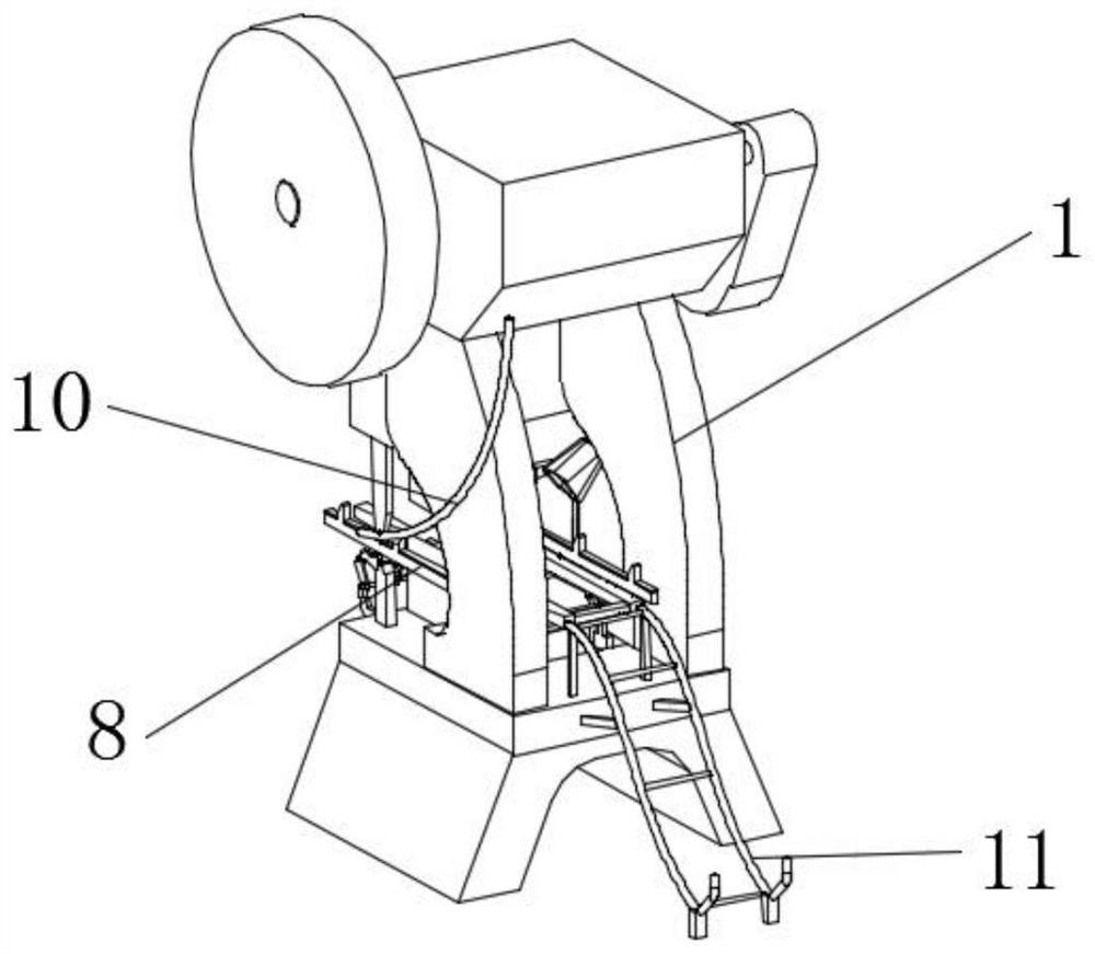
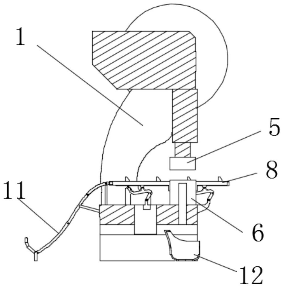
[0042] Example: Reference Figure 1-9 A new type of sheet metal stamping mechanical equipment that is convenient for stamping is shown, including a body 1, a support platform 7 is fixedly installed on the bottom side of the body 1, the top side of the support platform 7 is a support plane, and the bottom side is a stamping equipment supporting foot. One side is provided with a receiving rack 11, and the receiving rack 11 is used to collect the plate products after production. The side opposite to the receiving rack 11 on the body 1 is fixed with a telescopic chamber 4, and a punch is slidably installed in the telescopic chamber 4. The bottom end of the punch is fixedly equipped with an upper formwork 5, and the top side of the support platform 7 is fixedly equipped with a lower formwork 6, the upper formwork 5 and the lower formwork 6 are compatible, and the upper formwork 5 and the lower formwork 6 are respectively the parts of the plate stamping die. Upper mold and lower mol...


PUM


Abstract

The invention discloses novel plate stamping mechanical equipment convenient for stamping, and relates to the technical field of plate stamping mechanical equipment. The novel plate stamping mechanical equipment comprises a machine body, wherein a telescopic cavity is fixedly arranged in one side of the machine body; a punch is slidably arranged in the telescopic cavity; an upper die plate is fixedly arranged at the bottom end of the punch; a lower die plate is fixedly arranged at the top side of a supporting platform; the upper die plate is matched with the lower die plate; a driving mechanism is arranged at one side of the upper die plate; the driving mechanism is fixedly connected to the upper die plate; and material conveying rods are arranged at the two sides of the lower die plate. The novel plate stamping mechanical equipment is reasonable in structure and easy to operate, movement of the upper die plate is used for driving a multi-link mechanism to move, the two material conveying rods do parallel surrounding reciprocating motion, a stamped plate is jacked up by the material conveying rods and then continuously moves towards one side by a certain distance step by step, theaction that automatic feeding is conducted through the two material conveying rods and then automatic discharging is conducted is achieved, and the operation safety is improved.

Description

technical field [0001] The invention relates to the technical field of plate stamping machinery and equipment, in particular to a novel plate stamping machinery that is convenient for stamping. Background technique [0002] Stamping processing is a production technology that uses the power of conventional or special stamping equipment to directly deform the sheet metal in the mold to obtain product parts of a certain shape, size and performance. Sheet metal, molds and equipment are stamping The three elements of processing are divided into hot stamping and cold stamping according to the stamping processing temperature. The former is suitable for sheet metal processing with high deformation resistance and poor plasticity, while the latter is carried out at room temperature. It is a commonly used stamping method for thin plates. It is a metal plasticity One of the main methods of processing (or pressure processing), also belongs to material forming engineering technology. [...

Claims


Application Information

Patent Timeline
Patent Type & Authority Applications(China)
IPC IPC(8): B21D22/02B21D37/10B21D28/02B21D28/14B21D28/20B21D43/02B21D43/00B21D43/22B21D43/18B21D45/10B08B5/02B08B15/04
CPCB08B5/02B08B15/04B21D22/02B21D28/02B21D28/14B21D28/20B21D37/10B21D43/003B21D43/026B21D43/027B21D43/18B21D43/22B21D45/10
Inventor 徐建敏
Owner 德清县杰创机械有限公司
Learn More