
A liquid cavity heat dissipation device based on pool boiling heat dissipation

A technology of heat dissipation device and liquid cavity, which is applied in the direction of using liquid cooling for modification, cooling/ventilation/heating modification, electrical components, etc., can solve the problems of insufficient heat dissipation capacity, complex radiator structure, etc. Stable and efficient heat dissipation, small effective thickness

Active Publication Date: 2021-12-28
XI AN JIAOTONG UNIV
View PDF11 Cites 0 Cited by
  • Summary
  • Abstract
  • Description
  • Claims
  • Application Information

AI Technical Summary

Problems solved by technology

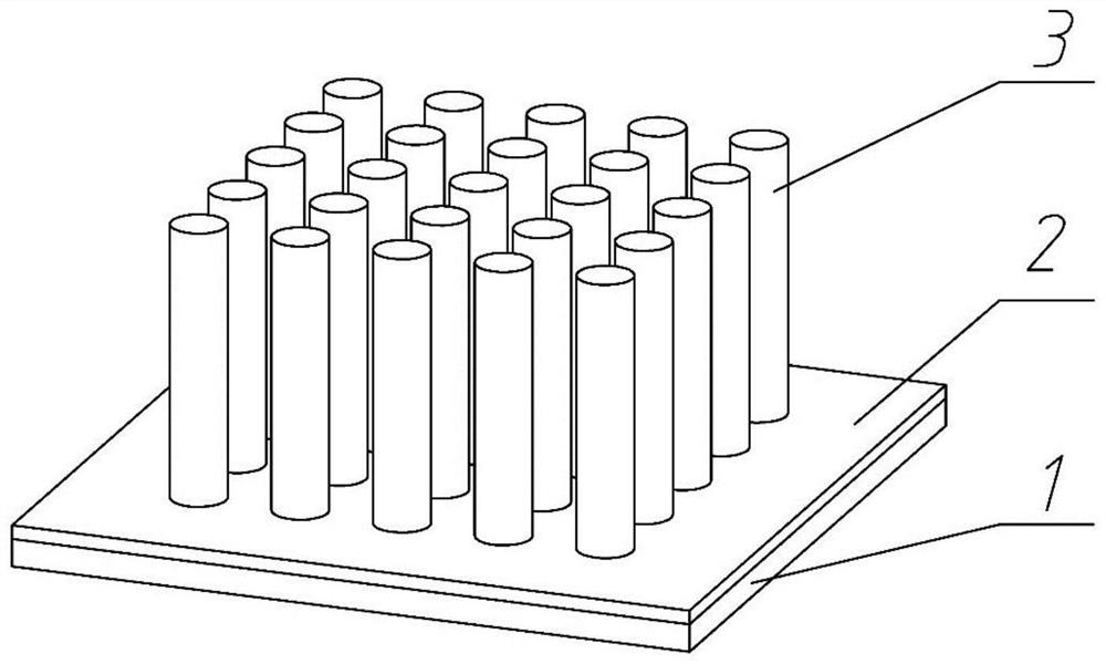
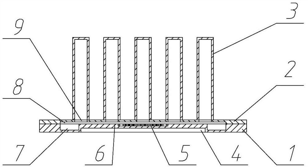
[0004] In order to solve technical defects such as complex internal structure and insufficient heat dissipation capacity of electronic device heat sinks in the prior art, the object of the present invention is to propose a liquid chamber (Liquid Chamber, LC) heat dissipation device heat sink based on pool boiling heat dissipation, which has The internal structure is simple, easy to process, and has a large heat dissipation capacity. The parameters of the structure can be customized according to the actual heat dissipation requirements.

Method used


Image

  • A liquid cavity heat dissipation device based on pool boiling heat dissipation
  • A liquid cavity heat dissipation device based on pool boiling heat dissipation
  • A liquid cavity heat dissipation device based on pool boiling heat dissipation

Examples


Embodiment 1

[0040] Such as Figure 5 As shown, the external cooling device consists of cooling fins and fans. Heat dissipation fins 10 and a fan 11 are installed outside the heat dissipation pipe 3 on the liquid cavity structure. The size parameters of the fan 11 and the size of the heat dissipation fins 10 are customized according to heat dissipation requirements and use environment. A plurality of through holes are opened on the heat dissipation fin 10 , and the size, quantity and arrangement of the through holes match the outer diameter, quantity and arrangement of the heat dissipation pipe 3 so that they can pass through the heat dissipation pipe 3 . The multi-layer heat dissipation fins 10 pass through the heat dissipation pipes 3 sequentially and are stacked, and are fixed and conduct heat with the heat dissipation pipes 3 by means of welding or stamping. A fan 11 is installed on both sides of the cooling fins 10 , and the two fans 11 are installed in the same direction, so as to ...

Embodiment 2

[0042] Such as Figure 6 ~ Figure 7 As shown, the difference between this embodiment and Embodiment 1 is that a cooling chamber 13 is installed outside the heat dissipation pipe 3 . One side of the cooling chamber 13 is provided with an inlet 12, and the other side is provided with an outlet 14. The cooling chamber 13 and the upper surface of the liquid chamber top plate 2 form a cooling chamber, which completely wraps the heat dissipation pipe 3, and the cooling chamber is completely filled with cooling liquid. According to different usage requirements, the coolant can be water, ethylene glycol, silicone oil and other working fluids. The low-temperature coolant flows into the cooling cavity from the inlet 12, conducts liquid forced convection heat exchange with the outer wall of the heat dissipation pipe 3, and flows out from the outlet 14. After being cooled by the external refrigerator, it flows in again from the inlet through the pump to realize the circulation of the cool...


PUM


Abstract

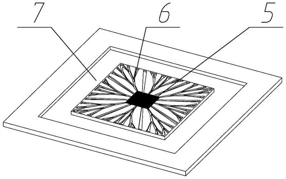
A liquid chamber heat dissipation device based on pool boiling heat dissipation includes a liquid chamber and an external heat dissipation device. The liquid chamber is composed of a bottom plate of the liquid chamber, a top plate of the liquid chamber and a heat dissipation pipe, and is filled with a phase change working fluid. The liquid phase-change working fluid absorbs the heat at the bottom of the boiling zone and undergoes boiling heat exchange to generate steam. The steam rises to the heat dissipation pipe through the through hole on the top plate of the liquid chamber, and is condensed into liquid by means of an air-cooled or water-cooled external heat sink and flows back into the liquid chamber. The compensation chamber and the liquid delivery area can effectively supply the phase change working medium to the boiling area. The invention adopts the heat exchange method of pool boiling and has strong heat dissipation capability. Compared with existing radiators designed based on steam chambers such as vapor chambers, it does not require a capillary core structure, is easy to process, and can effectively prevent internal evaporation while having a thinner thickness. It is suitable for heat dissipation of high-power heating equipment.

Description

technical field [0001] The invention belongs to the technical field of heat dissipation of electronic devices, and relates to a heat dissipation device, in particular to a liquid cavity heat dissipation device based on pool boiling heat dissipation. Background technique [0002] With the continuous improvement of the processing technology and process level of electronic devices, electronic chips are developing towards high integration, miniaturization and high frequency, which leads to a sharp increase in the heat generation per unit area of ​​the device, and is facing increasingly severe challenges. heat dissipation problem. If this part of the heat cannot be dissipated in time, the temperature of the device will continue to rise, which will significantly reduce the operating performance of the device, and even cause permanent damage to the device. Today, a sharp increase in temperature is a major factor in the failure of electronic devices. For highly integrated devices ...

Claims


Application Information

Patent Timeline
Patent Type & Authority Patents(China)
IPC IPC(8): H05K7/20
CPCH05K7/20336H05K7/20327H05K7/20309H05K7/20318H05K7/20136H05K7/20409
Inventor 魏进家周杰齐宝金刘蕾张永海
Owner XI AN JIAOTONG UNIV
Learn More