Wetting device for textile cloth

A wetting technology for textile cloth, which is applied in the field of textile wetting devices for textiles, and can solve problems such as uneven wetting process and flow reduction

Active Publication Date: 2021-11-30
绍兴达伽马纺织有限公司
View PDF7 Cites 0 Cited by
  • Summary
  • Abstract
  • Description
  • Claims
  • Application Information

AI Technical Summary

Problems solved by technology

[0005] The purpose of the present invention is to solve the problem that the deflection rod in the prior art reciprocates in the piston cylinder, and when the deflection rod slides to the outside of the piston cylinder, it can absorb water, so that the water outlet pipe can be wetted. However, when the deflection rod slides to the inside of the piston barrel, the water inside will be squeezed out, so that the flow of water in the outlet pipe will be reduced, so that there will be unevenness in the wetting process. Cloth wetting device

Method used


Image

  • Wetting device for textile cloth
  • Wetting device for textile cloth
  • Wetting device for textile cloth

Examples


Embodiment 1

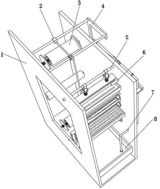
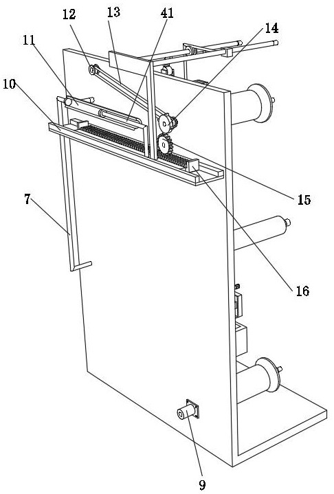
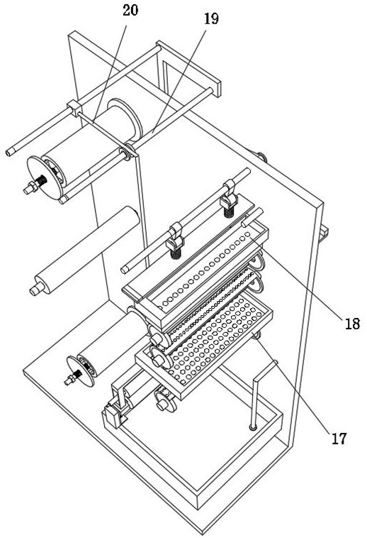
[0037] A wetting device for weaving textile fabrics for weaving, such as Figure 1-5 As shown, it includes a wetting frame 1 and a textile cloth winding mechanism. The inner walls on both sides of the wetting frame 1 are rotatably connected to the same cam column 5, and the inner walls on both sides of the wetting frame 1 are fixed with guard plates 28 by bolts. The top outer wall of the guard plate 28 is slidingly connected with two roller connecting posts 27, and the inner wall of the top of the two roller connecting posts 27 and the top outer wall of the guard plate 28 are snapped with a spring one 29, and the two rollers are connected to each other. The outer wall of the bottom of the column 27 is fixed with the same primary water receiving tank 18 by bolts, the outer wall of the bottom of the primary water receiving tank 18 is bonded with a water-absorbing sponge 30, and the inner walls of the two sides of the wetting frame 1 are respectively rotated and connected with a h...

Embodiment 2

[0044] A wetting device for weaving textile fabrics for weaving, such as Figure 8As shown, in order to ensure the smoothness and wetness of the remaining textile cloth after cutting the textile cloth; this embodiment makes the following improvements on the basis of embodiment 1: the inner wall of one side of the limiting plate 10 is clamped with a spring three 42 , and the end of the spring three 42 far away from the limiting plate 10 is clamped on the outer wall of the rack plate 16 side; Winding a certain length of textile cloth, cutting the textile cloth, thereby replacing the winding sleeve 25, wetting the remaining textile cloth on the winding sleeve one 3 and using a new winding sleeve again Tube two 25 is rolled, because spring three 42 is in compressed state in the process of one end of rack plate 16, so after the textile cloth is cut, winding sleeve one 3 circumference outer wall is owing to lost the tension force of textile cloth, will make The spring 3 42 resets, ...


PUM


Abstract

The invention discloses a wetting device for textile cloth for weaving, which relates to the technical field of wetting device for textile cloth; in order to reduce the dead angle of wetting on the surface of textile cloth; it specifically includes a wetting frame and a textile cloth winding mechanism. The inner wall is rotatably connected to the same cam column, and the inner walls on both sides of the wetting frame are fixed with guard plates by bolts. The outer wall of the top of the protective plate is clamped with a spring one, and the outer wall of the bottom of the two roller connecting columns is fixed with the same primary water tank by bolts, and the outer wall of the bottom of the primary water tank is bonded with a water-absorbing sponge. The inner walls on both sides are respectively connected with the first grooved roller, the second grooved roller and the third grooved roller. The present invention can place water by being provided with a primary water receiving tank, and more than two leakage holes are provided on the outer wall of the bottom of the primary water receiving tank, because the water-absorbing sponge has strong water-absorbing capacity.

Description

technical field [0001] The invention relates to the technical field of a wetting device for textile cloth, in particular to a wetting device for weaving textile cloth. Background technique [0002] The textile industry uses textile fabrics. Under different humidity conditions, their physical and mechanical properties (such as moisture regain, strength, elongation, softness and electrical conductivity, etc.) will change to varying degrees. For example, cotton fibers , when the relative humidity is 60%-70%, the dry state of the strong arm of the fiber can be increased by about 50%, so it needs to be wetted during the production of the textile fabric, so as to enhance its physical properties and improve the production quality. [0003] After retrieval, the Chinese patent application number is CN202010145807.X, which discloses a wetting device for weaving textile fabrics for weaving. Two groups of water outlet pipes, the two groups of outlet pipes are evenly distributed on the ...

Claims


Application Information

Patent Timeline
Patent Type & Authority Patents(China)
IPC IPC(8): D06B1/16D06B23/04D06B23/20D06C15/02
CPCD06B1/16D06B23/04D06B23/20D06C15/02
Inventor 胡达
Owner 绍兴达伽马纺织有限公司
Why Eureka
Try Eureka