Positioning fixture for clamping precision castings

A technology for positioning fixtures and precision castings, applied in the field of fixture tooling, which can solve the problems of accumulation of clamping errors, lateral or vertical displacement of parts, out of tolerance of parts, etc., and achieves the effect of reducing processing cycles, simple device structure, and simple structure.

Pending Publication Date: 2021-03-12
SICHUAN FUTURE AEROSPACE IND LLC
View PDF0 Cites 0 Cited by
  • Summary
  • Abstract
  • Description
  • Claims
  • Application Information

AI Technical Summary

Problems solved by technology

[0003] The purpose of the present invention is to solve the problem that parts tend to shift horizontally or vertically in the process of mechanical processing, and thus need to use machine tools for multiple clamping, which will easily lead to the accumulation of clamping errors and cause the parts to be out of tolerance. Positioning Fixtures for Clamping of Precision Castings

Method used


Image

  • Positioning fixture for clamping precision castings
  • Positioning fixture for clamping precision castings
  • Positioning fixture for clamping precision castings

Examples


Embodiment 1

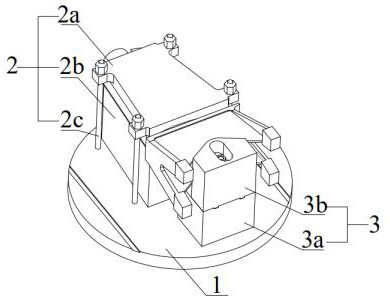
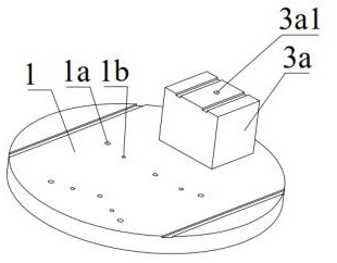
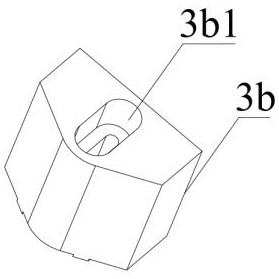
[0034] as attached figure 1 , attached figure 2 , attached image 3 And attached Figure 4As shown, after the precision casting is clamped by the positioning fixture, it is installed on the five-axis machine tool through the base 1. The base 1 of the positioning fixture is provided with a vertical pressing mechanism 2 and a horizontal pressing mechanism 3. Through the vertical pressing mechanism 2 Act on the upper and lower end surfaces of the precision casting, and press the precision casting vertically, so as to avoid the vertical movement of the precision casting when the holes at both ends of the precision casting are processed, through the horizontal compression mechanism 3 Press against the end of the precision casting along the lateral direction, thereby limiting the lateral movement of the precision casting during processing, thereby avoiding the lateral movement of the precision casting due to the lateral force when processing the outer end surface of the bayonet o...


PUM


Abstract

The invention belongs to the technical field of fixture tools, and particularly relates to a positioning fixture for clamping precision castings. The fixture comprises a base, and a vertical pressingmechanism and a transverse pressing mechanism are arranged on the base. The vertical pressing mechanism presses the upper end face and the lower end face of a to-be-machined part and is used for limiting vertical movement of the to-be-machined part. The transverse pressing mechanism abuts against the end of the to-be-machined part and is used for limiting transverse movement of the to-be-machinedpart, the vertical pressing mechanism acts on the upper end faces and the lower end faces of the precision castings to vertically press the precision castings, therefore vertical movement of the precision castings in the machining process is limited, the vertical pressing mechanism and the transverse pressing mechanism are matched to enable the part to be stably clamped, transverse and vertical displacement of the part in the machining process is avoided, the fixture is simple in structure, and the problems that in the machining process, the part is prone to transverse or vertical displacement, a machine tool needs to be adopted for repeated clamping, and out-of-tolerance of parts due to accumulation of clamping errors is easily caused are solved.

Description

technical field [0001] The invention belongs to the technical field of jigs and fixtures, in particular to a positioning jig used for clamping precision castings. Background technique [0002] For the machining of large precision castings for spacecraft, due to its complex shape, interrelated datums, and high requirements for drawing accuracy, it is difficult to clamp during machining, especially for the machining of holes at both ends of the assembly position. The position size and The shape and position tolerance requirements are high. When processing the end of the part, in order to ensure the machining accuracy, it is necessary to prevent the lateral movement of the part. Therefore, when clamping, the clamping tool that restricts the lateral movement of the part should be used mainly. During part processing, it is necessary to prevent the vertical movement of parts, so when clamping, the emphasis is on using clamping tools that limit the vertical movement of parts. The ...

Claims


Application Information

Patent Timeline
IPC IPC(8): B23Q3/06
CPCB23Q3/06
Inventor 梁朝晖张宇梁朝文潘继胜陈海方徐亮王萍谢长敏谭文川
Owner SICHUAN FUTURE AEROSPACE IND LLC
Why Eureka
Try Eureka