
Die-free spinning machining clamp

A dieless spinning and fixture technology, which is applied in the direction of manufacturing tools, metal processing equipment, feeding devices, etc., can solve the problems of narrow application range, high production cost, and low spinning production efficiency, and achieve strong versatility and clamping The effect of maintaining high stability and reducing the cost of line transfer

Pending Publication Date: 2021-03-12
广东博赛数控机床有限公司
View PDF0 Cites 1 Cited by
  • Summary
  • Abstract
  • Description
  • Claims
  • Application Information

AI Technical Summary

Problems solved by technology

[0004] In order to solve the problems that the spinning machine tools in the prior art need to be assisted by molds or tail tops, the production cost is high, the spinning production efficiency is low, and the use range is narrow, the object of the present invention is to provide a moldless spinning jig

Method used


Image

  • Die-free spinning machining clamp
  • Die-free spinning machining clamp
  • Die-free spinning machining clamp

Examples


Embodiment Construction

[0029] The technical solutions of the present invention will be described in further detail below in conjunction with specific embodiments and accompanying drawings, but the protection scope and implementation methods of the present invention are not limited thereto. In the description of the embodiments of the present invention, it should be noted that the orientation or positional relationship indicated by "left" and "right" in terms is based on the orientation or positional relationship shown in the drawings, or the Orientation or positional relationship that is conventionally placed, or is only used to distinguish the description, is only for the convenience of describing the present invention and simplifying the description, and does not indicate or imply that the referred device or element must have a specific orientation, be configured in a specific orientation, and operation, and therefore should not be construed as limiting the invention, still less as indicating or im...


PUM


Abstract

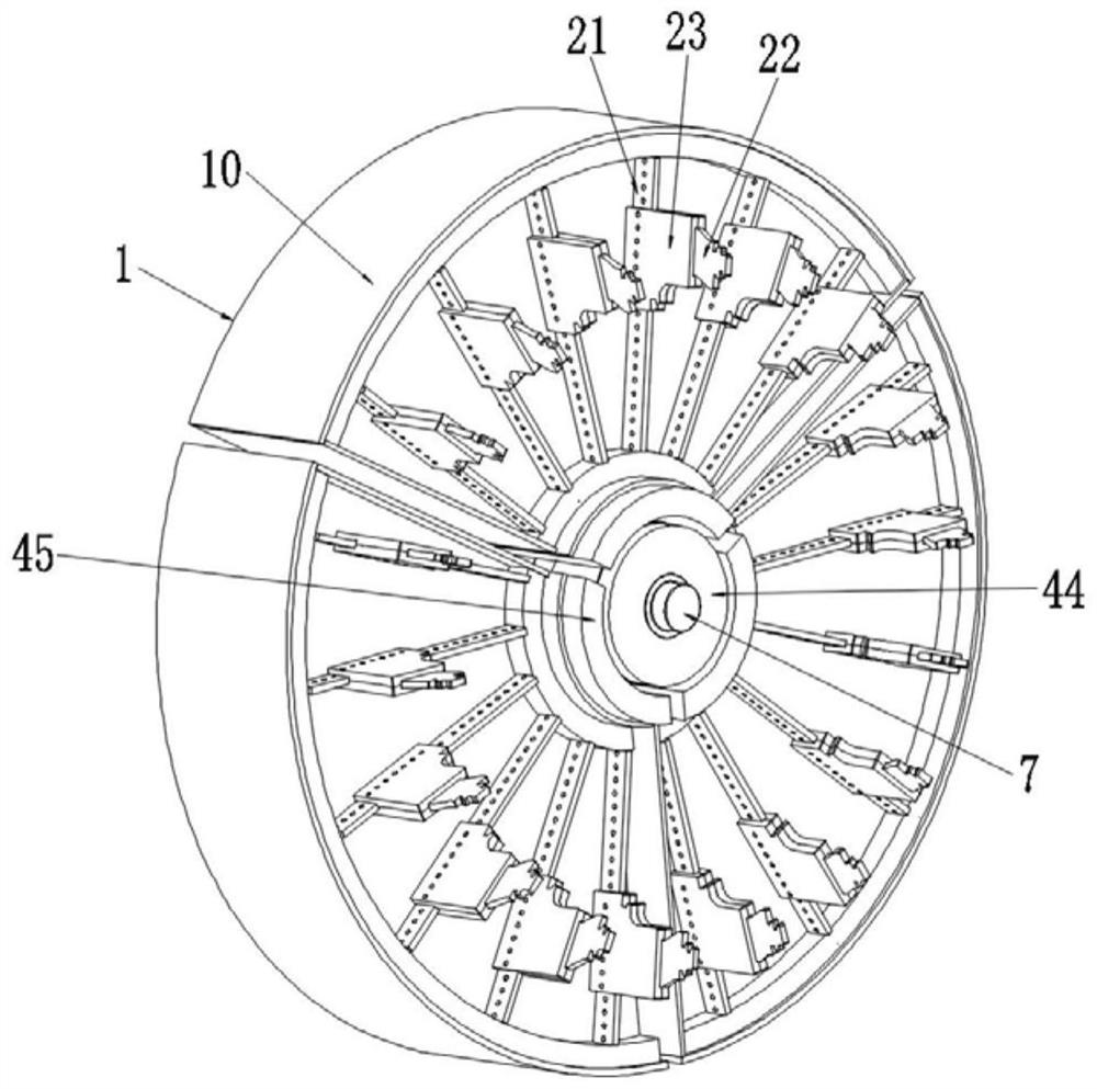
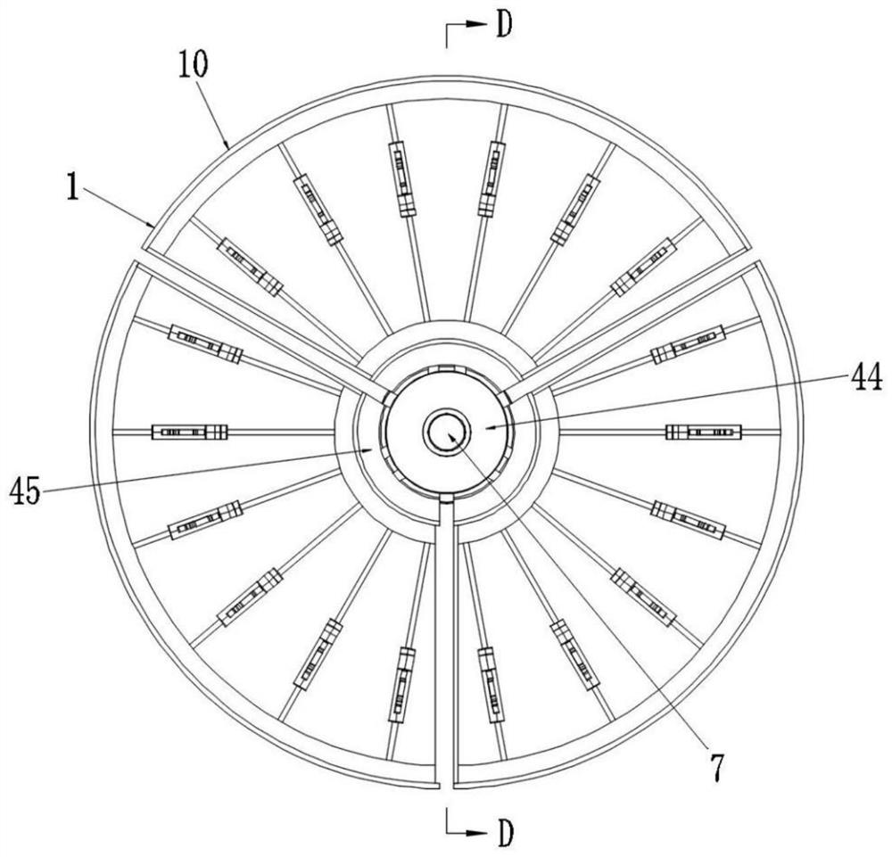
The invention discloses a die-free spinning machining clamp. The die-free spinning machining clamp comprises a clamp disc. The clamp disc is divided into a plurality of clamp petals; a plurality of clamping assemblies are uniformly distributed on clamping surfaces of the clamp petals around the center of the clamp disc; a rotary power transmission assembly is arranged in the center of the clamp disc and used for being connected with a spinning spindle and transmitting power to drive the clamp disc to rotate; a clamp petal traction assembly is further arranged in the center of the clamp disc; the clamp petal traction assembly comprises outer supporting guide rods penetrating through the rotary power transmission assembly; the outer supporting guide rods are connected with the clamp petals through outer supporting pull rods; and the plurality of clamp petals can be folded or separated along the radial direction along with the axial movement of the outer supporting guide rods. The die-free spinning machining clamp is high in universality, wide in size range and variety range of clamped machined parts, free of assistance of a die or a tail ejector, capable of effectively reducing the production cost and improving the spinning production efficiency and suitable for fixing various hollow thin-wall materials.

Description

technical field [0001] The invention relates to the technical field of spinning equipment, in particular to a moldless spinning fixture. Background technique [0002] Spinning, as an important processing and production method, is widely used in product forming and processing, and is mainly used in the production of large-scale heavy industry products, including the production of thin-walled tubular products and ring products such as tuyere products and aerospace products. During the spinning process, the workpiece needs to be clamped by a fixture, and the spinning process is performed under the rotation drive of the spinning spindle. [0003] For existing horizontal and vertical spinning machine tools, etc., the spinning fixtures used in spinning are usually custom-made fixtures with a small scope of application, and usually require molds for auxiliary positioning. When processing blanks of different shapes and sizes, it is necessary to replace different fixtures or perform...

Claims


Application Information

Patent Timeline
IPC IPC(8): B21D22/14B21D43/00
CPCB21D22/14B21D43/003
Inventor 周路周平虎邱月华童兆军冯诗荣黄晓楚
Owner 广东博赛数控机床有限公司
Learn More