Wood surface paint spraying device

A technology for wood surface and paint storage, applied in the field of wood processing, can solve the problems of high requirements for personnel operation and high cost, and achieve the effects of improving stability, improving mixing effect and avoiding deposition phenomenon.

Inactive Publication Date: 2021-03-12
景春霞
View PDF6 Cites 0 Cited by
  • Summary
  • Abstract
  • Description
  • Claims
  • Application Information

AI Technical Summary

Problems solved by technology

[0003] Traditional wood spraying devices need to use complex rotating and moving components to ensure the flexibility of the spraying mechanism when spraying some columnar wood, so as to ensure the uniform spraying of the wood surface, resulting in high overall cost of the device and the operation of personnel. High requirements, so there are certain limitations

Method used


Image

  • Wood surface paint spraying device
  • Wood surface paint spraying device
  • Wood surface paint spraying device

Examples


Embodiment 1

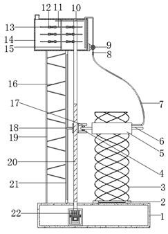
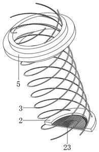
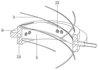
[0029] refer to Figure 1-4 , a wood surface painting device, comprising a chamber seat 1, the top outer wall side of the chamber seat 1 is fixed with a bottom 2 by bolts, the top outer wall of the bottom 2 is welded with a spiral rib tube 3, and one end of the spiral rib tube 3 is passed The ring cylinder 5 is threadedly connected, the inner wall side of the cavity seat 1 is fixed with a servo motor 22 by bolts, and the output shaft of the servo motor 22 is connected with a threaded column 20 through a coupling, and the top outer wall of the cavity seat 1 is vertically vertical on both sides at one end. The fixed support plate 21 and the side vertical bar 19 are directly welded, and the top of the fixed support plate 21 and the side vertical bar 19 is welded with the same paint storage bucket 14, and one end of the paint storage bucket 14 is connected with the driven rod 15 through bearing rotation, And the driven rod 15 is welded with equidistantly distributed fixed arm bars...

Embodiment 2

[0039] refer to Figure 5, a wood surface painting device, compared with Embodiment 1, this embodiment also includes a side of the movable scraper 13 fixedly equipped with a callback cylinder 26 distributed equidistantly; the callback cylinder 26 arranged on the movable scraper 13, It can be folded along with the movable scraper bar 13 to improve the callback effect of the paint.

[0040] In the present invention, the callback cylinder 26 is provided with cross-through grooves 27; during the callback process of the paint, the paint can be randomly extruded from the cross-through grooves 27, which is beneficial to further improve the chaos of the paint.

[0041] When the present invention is in use: through the dial-back cylinder 26 of the movable scraper 13 and the cross-through groove 27 on the dial-back cylinder 26, the movable scraper 13 can be folded to improve the dial-back effect on the paint, and the paint will During the callback process, it can be extruded at the cro...


PUM


Abstract

The invention belongs to the technical field of wood processing, particularly relates to a wood surface paint spraying device. The problems that most of traditional wood paint spraying devices adopt complex rotating and moving assemblies to achieve paint spraying on wood, the cost is high, and operation is not easy are solved. According to the scheme, the device comprises a cavity base, a supporting bottom is fixed to one side of the outer wall of the top of the cavity base through bolts, a spiral rib barrel is welded to the outer wall of the top of the supporting bottom, one end of the spiralrib barrel is connected with an annular barrel through threads, a servo motor is fixed to one side of the inner wall of the cavity base through bolts, and an output shaft of the servo motor is connected with a threaded column through a coupler. By arranging the servo motor, a spiral column can be driven to rotate, under the limiting effect of a fixed supporting plate, a movable block is driven tomove in the vertical direction, meanwhile, under the effect of balls and the spiral rib barrel, the annular barrel is made to rotate while the annular barrel is pushed to move up and down, and therefore uniform paint spraying treatment on wood is achieved.

Description

technical field [0001] The invention relates to the technical field of wood processing, in particular to a wood surface painting device. Background technique [0002] Wood is the lignified tissue of plants capable of secondary growth, such as trees and shrubs. After the primary growth of these plants ends, the vascular cambium in the rhizome becomes active, developing bast outward and wood inward. Wood is the general term for plant tissues that develop inwardly from the vascular cambium, including xylem and parenchyma rays. Wood plays a great supporting role in human life. According to the different properties and characteristics of wood, people use them in different ways. Wood is widely used in the field of furniture, such as beds, cabinets, tables, chairs, etc., and even the handrails of stairs are also widely used. [0003] Traditional wood spraying devices need to use complex rotating and moving components to ensure the flexibility of the spraying mechanism when spra...

Claims


Application Information

Patent Timeline
Patent Type & Authority Applications(China)
IPC IPC(8): B05B13/04B05B13/02B05B15/25
CPCB05B13/02B05B13/041B05B13/0421B05B15/25
Inventor 景春霞
Owner 景春霞
Why Eureka
Try Eureka