
Modular intelligent clean room

A clean room, modular technology, applied in the field of clean room, can solve the problems of inconvenient disassembly and installation, low structural strength, high internal temperature, etc., and achieve the effect of convenient riveting, compact structure and smaller volume

Pending Publication Date: 2021-03-09
南通市德信致远环境科技有限公司
View PDF0 Cites 0 Cited by
  • Summary
  • Abstract
  • Description
  • Claims
  • Application Information

AI Technical Summary

Problems solved by technology

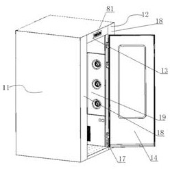
There is a seal between the door of the air shower and the air shower, and a sealed frame will be designed inside the door. In the past, when the air shower was in use, the staff opened the door on the side of the air shower to enter the central room of the air shower. Start the work of the air shower room, the fan suddenly starts to suck air, causing the air pressure near the fan inside the air shower room to suddenly decrease, and then the fan blows the wind from the upper part of the air shower room and the middle upper position on both sides to the human body to remove dust. At this time, the air pressure in the central room suddenly increases again. Although the fan starts for 10-20 seconds, the moment the fan starts, the internal pressure difference will interact with the outside air pressure, which will cause the doors on both sides of the air shower to shake. It will cause great damage to the door lock. After the fan stops, the air pressure in the central chamber will continue to be high for a period of time, and the door will be forced outward by the air pressure, which will cause great damage to the door lock and make it difficult to open the door lock. You need to wait for 3-5 seconds The door lock can be opened smoothly only after the air pressure inside the shower room is constant
At the same time, some air showers are now airtight, which will lead to high internal temperature in summer and make people feel uncomfortable.
[0006] There is also the design and structure of the static pressure box of the air shower. During the production process, the filter needs to fill the side wall of the static pressure box. The filter requires a large volume, and the bracket for installing the filter is welded to the air shower. On the outer wall panel of the side wall, the welding process will cause the deformation of the outer wall panel; the filter was also connected to the front side of the support frame by glue or bolts in the past, which is troublesome
Existing air showers are traditionally displayed with indicator lights, and it is impossible to achieve information interaction between the air shower state and the outside personnel waiting for the shower
[0007] In the past, when welding the hanger used in the dressing room of the clean room, the first thing to do is to cut the material, the cylindrical clothes hanging rod and several hanging rings, the two ends of the cylindrical clothes hanging rod are fixed on the vise, and the clothes hanging rod is passed through the measuring ruler. Mark the positions for welding the hanging rings one by one. The staff holds the hanging rings with pliers and welds them on the clothes rail. When welding, they are subjected to stress, the direction of the hanging rings is not uniform, it is not beautiful, and the distance between the hanging rings cannot Uniform control, not convenient for subsequent hanging clothes
[0008] In the past, the cover plate of the clean room was generally directly fixed to the back plate of the clean room by bolts, which was very inconvenient to disassemble and install.
In the past, the design of the window on the door of the clean room is to directly open a window shape on the door and then install the glass barrier. The glass barrier is welded to the window, and then the glass is glued to the glass barrier, which is inconvenient to install. The structural strength is relatively low

Method used


Image

  • Modular intelligent clean room
  • Modular intelligent clean room
  • Modular intelligent clean room

Examples


Embodiment Construction

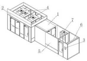
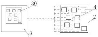
[0081] Refer to attached Figure 1-48 , a modular intelligent clean room, which includes a changing unit, an air shower room 1, and a clean room 2. A changing unit is installed on the entrance side of the clean room 2. The air shower room 1 is located inside the changing unit and the air shower room 1 is installed in the clean room. At the entrance of room 2, the monitoring unit 3 is installed on the outer wall of the entrance of the changing unit. Several fan filter units 4 are installed on the top of the clean room 2. The monitoring unit 3 is designed to be installed on the outside of the clean room 2 or clean room 2 Inside the room and the monitoring unit 3 is connected to several fan filter units 4 through signal lines; the monitoring unit 3 is designed to monitor several fan filter units 4 and display that several fan filter units 4 are arranged one by one on the top of the clean room 2 Cloth display unit 30; the dressing unit includes a dressing room 5, a hanger 6, and a...


PUM


Abstract

The invention relates to a modular intelligent clean room. The modular intelligent clean room comprises a dressing unit, an air shower and a clean room body, wherein the dressing unit is installed onthe inlet side of the clean room body; the air shower is located in the dressing unit and installed at an inlet of the clean room; a monitoring unit is installed on the outer wall of an inlet of the dressing unit; a plurality of blower filtration units are installed on the top of the cleaning room body; display units which are used for monitoring the blower filtration units and displaying the one-to-one arrangement of the blower filtration units on the roof of the clean room body are designed on the monitoring unit; and the dressing unit comprises a dressing room, a hanging rack and a self-cleaning glove box. The modular intelligent clean room has the advantages that the design is simple; the clean room is convenient to use; the combined air shower and dressing room are designed in the clean room; the self-cleaning glove box and the hanging rack are further designed in the dressing room; so that it is convenient for a worker to well prepare for work before entering a workplace; the structure is compact; and the design is reasonable.

Description

technical field [0001] The invention relates to the technical field of clean rooms, in particular to a modular intelligent clean room. Background technique [0002] Clean rooms are mainly used in the electronic information industry, such as integrated circuits, flat panel displays, electronic components and other high-tech fields. The requirements for product processing accuracy and integration are getting higher and higher, and many of them need to be produced in a clean environment. At present, there are still some deficiencies in the production and use of clean rooms. [0003] In the past, several fan filter units were installed on the top of the clean room. The position of the fan filter units installed in the clean room was irregular according to the actual production. The installers only numbered several fan filter units, and the monitoring system connected several Once the fan filter unit is overloaded or broken, the monitoring system will only show that there is a p...

Claims


Application Information

Patent Timeline
Patent Type & Authority Applications(China)
IPC IPC(8): B08B5/02B08B13/00B01D46/10
CPCB08B5/02B08B13/00B01D46/10
Inventor 蔡立东
Owner 南通市德信致远环境科技有限公司
Learn More