Automatic spraying device for lifting process of wire cutting machine

An automatic spraying and wire-cutting technology, which is applied to fine working devices, stone processing equipment, manufacturing tools, etc., can solve the problems of insufficient spraying effect, spraying dead angle, small spraying area, etc., and achieve good spraying The effect of spraying and sweeping, adapting to line cutting operations, and avoiding dead ends of spraying

Inactive Publication Date: 2021-03-05
LIANCHENG KEKESI TECH CO LTD
View PDF12 Cites 0 Cited by
  • Summary
  • Abstract
  • Description
  • Claims
  • Application Information

AI Technical Summary

Problems solved by technology

[0003] According to the technical scheme described in the published authorization announcement number CN 105397170 B, an automatic spraying device in the process of feeding DW wire cutting machine, the structure is simple and easy to use, and it is applied in the process of wire cutting and feeding to wash silicon The silicon mud on the surface of the wafer makes the silicon wafer meet the standard of the cleaning process, reduces the soaking time of the silicon wafer, and improves the cleaning capacity. The surface of the silicon wafer is less dirty. In the technical plan, the spraying structure can cooperate with the movement during the material lifting process, but the effect of spraying and rinsing is not considered, and a better spraying effect cannot be achieved.
[0004] In the wire cutting machine, due to the simple and single spraying structure, the spraying direction of the water is single when spraying, and it is easy to produce a spraying dead angle when the material is cut, the spraying is not thorough, and the spraying area is small, which affects the overall spray effect

Method used


Image

  • Automatic spraying device for lifting process of wire cutting machine
  • Automatic spraying device for lifting process of wire cutting machine
  • Automatic spraying device for lifting process of wire cutting machine

Examples


Embodiment approach

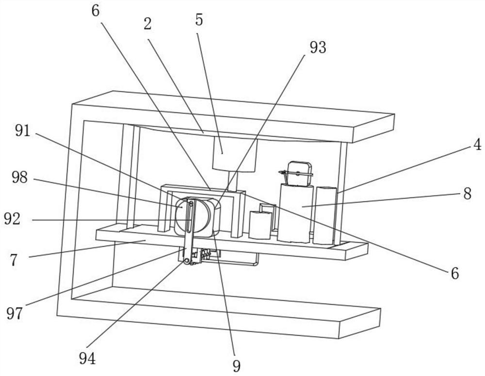
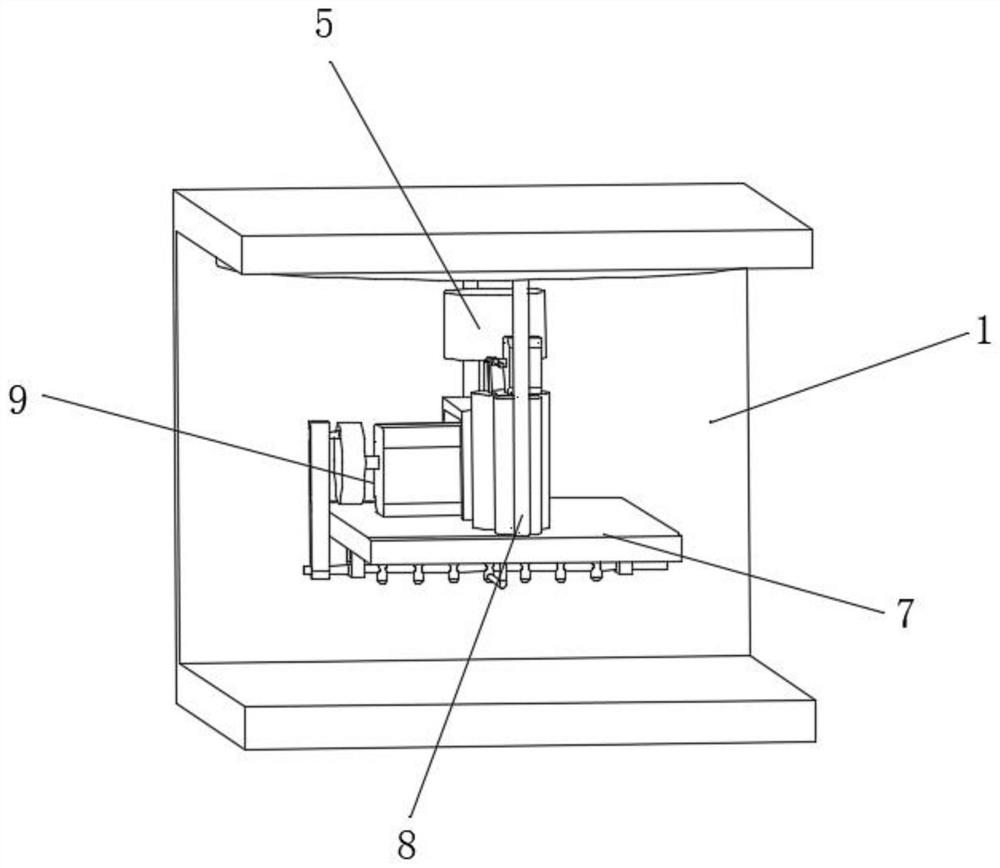
[0028] As an embodiment of the present invention, the spraying structure 9 includes a toggle lever 91, a slide hole 92, a swing motor 93, a swing shaft 94, a spray head 95, a swing frame 96, a swing lever 97 and a rotating disk 98. The motor 93 is mounted on the top side of the support plate 7 through bolts. The rotating shaft of the swing motor 93 is fitted with a rotating disk 98. The eccentric position of the end face of the rotating disk 98 is welded with a toggle lever 91. The swing frame 96 is welded on the bottom side of the support plate 7, and the swing shaft 94 is installed in the swing frame 96 through bearings. The circumferential surface of the swing shaft 94 is equipped with a plurality of shower heads 95 in parallel. The bottom end of the swing rod 97 It is welded on one end of the swing shaft 94 , and the top of the swing rod 97 is provided with a slide hole 92 .

[0029] As an embodiment of the present invention, the toggle rod 91 is fitted in the slide hole 9...


PUM


Abstract

The invention discloses an automatic spraying device for the lifting process of a wire cutting machine. The automatic spraying device comprises a rack, a rail, a sliding buckle, a hanging rod, a rotating motor, a connecting frame, a supporting plate, a flow limiting structure and a spraying structure, wherein the rail is fixed on the bottom side of a top transverse plate of the rack, a sliding block is embedded in the rail in a matched mode, the spraying structure is installed in the middle of the supporting plate, and the flow limiting structure is installed at the edge of the top side of thespraying structure. According to the automatic spraying device, the spraying structure is arranged, a swing motor works to drive a rotating disc to rotate, so that the rotation of a shifting rod canbe realized, the shifting rod slides along a sliding hole, the swing of a swing shaft can be realized, in the swing process, multi-angle spraying of materials can be realized, the generation of spraying dead corners is avoided, the rotating motor works synchronously to drive the connecting frame to rotate, under the sliding fit of the sliding block along the rail, the rotation of the supporting plate can be realized, the rotation of a plurality of spray heads can be realized synchronously, a better spraying and sweeping effect can be achieved, and a better spraying effect can be achieved.

Description

technical field [0001] The invention relates to the technical field of wire cutting machines, in particular to an automatic spraying device used in the material lifting process of the wire cutting machine. Background technique [0002] The wire cutting machine is mainly composed of three parts: machine tool, numerical control system and high frequency power supply. The numerical control system is composed of a single-chip microcomputer, a keyboard, and a frequency conversion detection system. It has main functions such as gap compensation, linear interpolation, circular interpolation, and automatic processing of broken wires. It can cut materials such as high strength, high toughness, high hardness, and high brittleness. Magnetic materials, as well as precision small and complex-shaped parts. Wire cutting technology and wire cutting machine tools are being widely used in all walks of life; [0003] According to the technical scheme described in the published authorization ...

Claims


Application Information

Patent Timeline
Patent Type & Authority Applications(China)
IPC IPC(8): B28D5/00B28D5/04
CPCB28D5/04B28D5/0076
Inventor 李小锋寿晨曦杨永远段世飞江佳飞
Owner LIANCHENG KEKESI TECH CO LTD
Why Eureka
Try Eureka