Rolling device for realizing various super-hydrophobic surface microstructure morphologies and application method of rolling device

A technology of super-hydrophobic surface and rolling device, applied in the field of rolling device, can solve the problems such as the inability to prepare surfaces with different microstructures in a large area, and the preparation process of microstructured surfaces is complicated, so as to improve the preparation speed, reduce labor consumption, Equipment simple effect

Active Publication Date: 2021-03-02
JIANGSU UNIV OF TECH
View PDF5 Cites 1 Cited by
  • Summary
  • Abstract
  • Description
  • Claims
  • Application Information

AI Technical Summary

Problems solved by technology

[0005] In order to solve the technical problems of complex microstructure surface preparation process and the inability to prepare large-area surfaces with different microstructure topography in the existing method, it provides a variety of super-hydrophobic surfaces Rolling device for microstructure topography and its application method

Method used


Image

  • Rolling device for realizing various super-hydrophobic surface microstructure morphologies and application method of rolling device
  • Rolling device for realizing various super-hydrophobic surface microstructure morphologies and application method of rolling device
  • Rolling device for realizing various super-hydrophobic surface microstructure morphologies and application method of rolling device

Examples


Embodiment 1

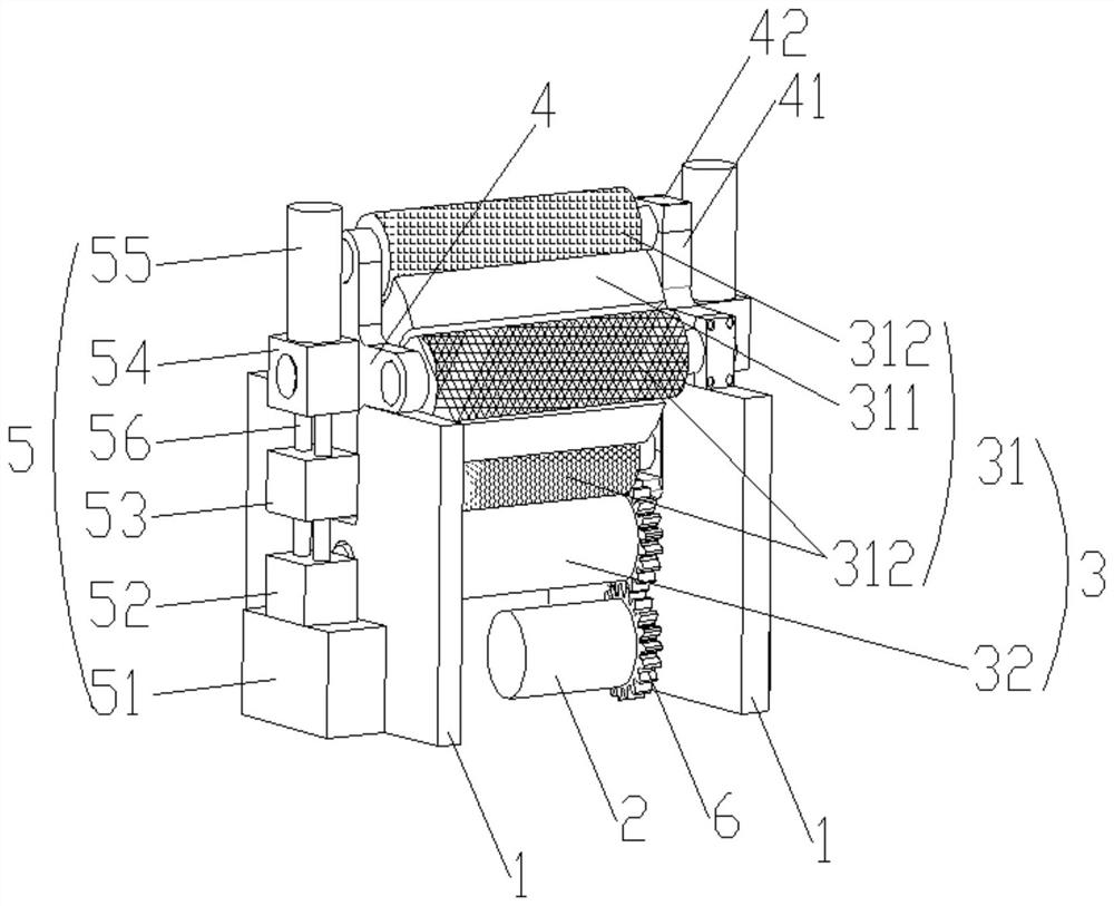
[0027] A rolling device that realizes a variety of superhydrophobic surface microstructure topography, the schematic diagram of which is shown in figure 1 As shown, it includes a base 1 and a driving mechanism 2 and a pressure roller part 3 arranged in the base 1 in order from bottom to top. connect;

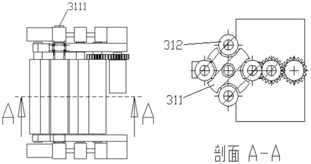
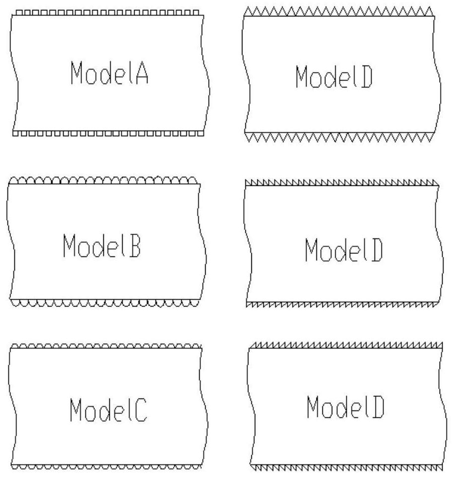
[0028] The pressure roller part 3 comprises an upper pressure roller group 31 and a lower pressure roller 32, and the upper pressure roller group 31 comprises an upper pressure roller frame 311 and four upper pressure rollers 312 with different surface topography installed around the upper pressure roller frame 311. An upper pressure roller 312 is detachably connected with the upper pressure roller frame 311, and the upper pressure roller frame 312 is movably installed on the base 1, and the two ends of the lower pressure roller 32 are installed on the base 1; one of the upper pressure rollers 312 is connected with the lower pressure roller The rollers 32 are parallel and leave...


PUM

PropertyMeasurementUnit
diameteraaaaaaaaaa
heightaaaaaaaaaa
contact angleaaaaaaaaaa

Abstract

The invention relates to a rolling device for realizing various super-hydrophobic surface microstructure morphologies and an application method of the rolling device. The rolling device comprises a base, a driving mechanism and a compression roller part, wherein the compression roller part comprises an upper compression roller group and a lower compression roller, the upper compression roller group comprises an upper compression roller frame and a plurality of upper compression rollers which are arranged on the upper compression roller frame and have different surface morphologies, the upper compression rollers are detachably connected with the upper compression roller frame, the upper compression roller frame is movably arranged on the base, and the two ends of the lower compression roller are installed on the base; one of the upper compression rollers is parallel to the lower compression roller, and a gap is reserved between the upper compression roller parallel to the lower compression roller and the lower compression roller and used for containing to-be-machined base materials; protrusions arranged on the surfaces of the upper compression rollers in an arrayed mode to form a surface morphology; the base is further provided with a roller distance adjusting part, and the roller distance adjusting part is connected with the upper compression roller frame and used for driving the upper compression roller frame to move on the base; and the driving mechanism is installed on the base and used for driving the lower compression roller to roll. According to the rolling device, the microstructure of the surface to be machined can be built through rolling of the compression rollers, and therefore the super-hydrophobicity of the surface of a material is achieved.

Description

technical field [0001] The invention relates to the technical field of super-hydrophobic surface manufacturing, in particular to a rolling device and an application method for realizing various super-hydrophobic surface microstructure topography. Background technique [0002] The superhydrophobic surface has the properties of self-cleaning, anti-corrosion, drag reduction, anti-icing and friction resistance. It can be used in industries such as ships, aerospace and pipeline transportation, and has a good application prospect. For example, self-cleaning windshields and rearview mirrors can effectively avoid the impact of weather on the driver's vision in rainy, snowy, foggy and frosty environments, reduce blind spots and blurred vision, and improve driving safety. In the biomedical industry, superhydrophobic materials can prevent dirt, cell adsorption, and have better biocompatibility. In the kitchen and home furnishing, the use of self-cleaning surfaces can reduce the depos...

Claims


Application Information

Patent Timeline
Patent Type & Authority Applications(China)
IPC IPC(8): B29C59/04B81C1/00
CPCB29C59/043B29C59/002B81C1/00015
Inventor 叶霞徐胜冯欢陆磊
Owner JIANGSU UNIV OF TECH
Why Eureka
Try Eureka