
High-rate lithium iron phosphate battery and preparation method thereof

A lithium iron phosphate battery, high-rate technology, applied in the direction of secondary batteries, circuits, electrical components, etc., can solve safety problems, limit the rate performance of lithium iron phosphate batteries, and the decomposition of positive electrode materials, so as to improve capacity and energy density , good electronic conductivity, and the effect of reducing the internal resistance of the battery

Pending Publication Date: 2021-02-26
安徽理士新能源发展有限公司
View PDF0 Cites 0 Cited by
  • Summary
  • Abstract
  • Description
  • Claims
  • Application Information

AI Technical Summary

Problems solved by technology

[0003] At present, the main methods to improve the rate performance of lithium-ion batteries are: 1. Relevant replacement or modification of positive and negative electrode materials, but this method is technically difficult and difficult to make major breakthroughs; 2. Using different types of electrolytes, Such as solid electrolyte, etc., to improve the safety of the battery; however, this method is technically difficult and difficult to apply in a short time; 3. The method of coating the current collector with carbon increases the contact area between the active material and the current collector, thereby reducing the charge transfer resistance and improving The rate performance of the battery; however, due to the high temperature of the battery under high rate conditions, it is easy to cause the diaphragm to melt and the positive electrode material to decompose, causing serious safety problems
[0004] Lithium iron phosphate with a polyanionic structure has the advantages of high structural stability, low decomposition temperature, and stable discharge platform, making it the first choice for high-safety lithium-ion battery cathode materials, but lithium iron phosphate itself has poor conductivity, which severely limits the ability of phosphoric acid Rate performance of lithium iron batteries

Method used


Image

  • High-rate lithium iron phosphate battery and preparation method thereof
  • High-rate lithium iron phosphate battery and preparation method thereof
  • High-rate lithium iron phosphate battery and preparation method thereof

Examples


preparation example Construction

[0053] A preparation method of a high-rate lithium iron phosphate battery, the method comprising the following steps:

[0054] S1: Making pole pieces:

[0055] Including the production of positive pole pieces:

[0056] Mix the active material, conductive agent and dispersant, then add the solvent to obtain the positive electrode slurry, and keep the solid content at 50-70%; then coat the positive electrode material on the surface of the positive electrode substrate, dry, roll, and cut Afterwards, the positive pole piece is obtained;

[0057] To make the negative pole piece:

[0058] Mix active material, conductive agent and dispersant, then add solvent to obtain negative electrode slurry, keep the solid content at 45-55%; then coat the negative electrode material on the surface of the negative electrode substrate, dry, roll, and cut Afterwards, the negative pole piece is obtained;

[0059] S2: Making batteries and packaging:

[0060] Laminate a plurality of positive elect...

Embodiment example 1

[0078] (1) Making the positive electrode sheet: mix lithium iron phosphate, graphene, carbon nanotubes and polyvinylidene fluoride according to a certain mass ratio, and use N-methylpyrrolidone as a solvent to make positive electrode slurry, and keep the solid content at 55-56%, and then apply it continuously and evenly on the carbon-coated aluminum foil, and obtain the positive pole piece after drying, rolling and cutting;

[0079] (2) Making the negative electrode sheet: mix graphite, graphene, carbon nanotubes and polyvinylidene fluoride according to a certain ratio, and keep the solid content at 50-51%; then apply it continuously and evenly on the carbon-coated copper foil , after drying, rolling, and slitting, the negative electrode sheet is obtained;

[0080] (3) Production of battery cells: Laminate the positive pole piece, diaphragm and negative pole piece to form a battery core, weld the tabs, and package them with aluminum-plastic film to obtain a battery;

[0081] ...

Embodiment example 2

[0087] (1) Making the positive electrode sheet: mix lithium iron phosphate, carbon nanofiber, Super P and polyvinylidene fluoride according to a certain mass ratio, and use N-methylpyrrolidone as the solvent to make the positive electrode slurry, and keep the solid content at 57-59%, and then apply it continuously and evenly on the carbon-coated aluminum foil, dry, roll, and cut to get the positive electrode sheet;

[0088] (2) Making the negative electrode sheet: keep the solid content of graphite, carbon nanofiber, Super P and polyvinylidene fluoride at 50-51%, and then apply it continuously and evenly on the carbon-coated copper foil, and dry and roll Negative pole pieces are obtained after pressing and cutting;

[0089] (3) Production of battery cells: Laminate the positive pole piece, diaphragm and negative pole piece to form a battery core, weld the tabs, and package them with aluminum-plastic film to obtain a battery;

[0090] (4) Battery baking: put the battery into a...


PUM


Abstract

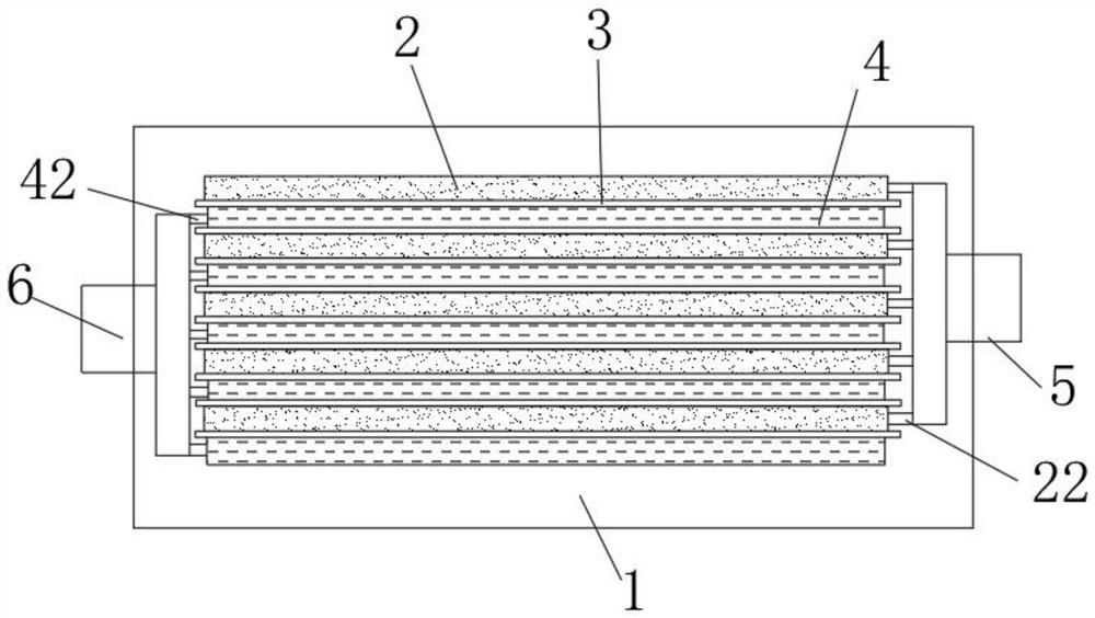
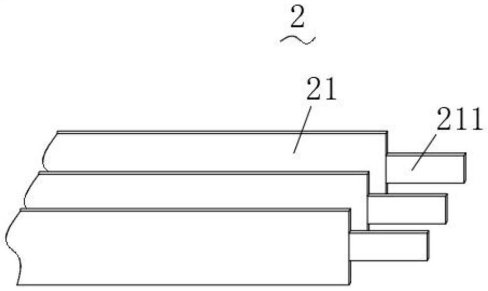
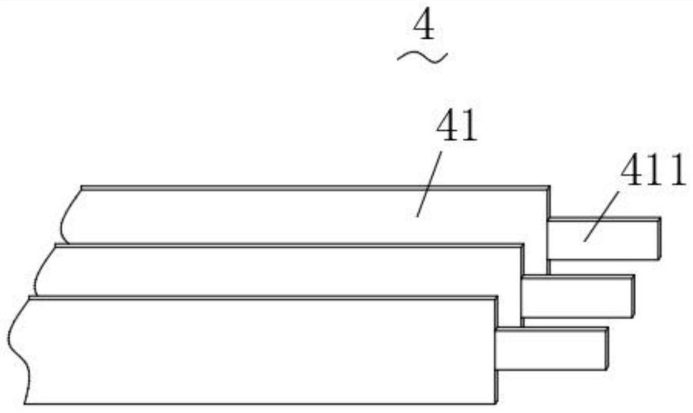
A high-rate lithium iron phosphate battery comprises an aluminum-plastic film and a battery cell, the aluminum-plastic film forms a closed cavity, and the battery cell is arranged in the cavity; the battery cell comprises a positive plate, a diaphragm, a negative plate, an aluminum tab and a nickel tab, the positive plate, the diaphragm and the negative plate are stacked in sequence, and the diaphragm separates the positive plate from the negative plate; the positive plate is formed by superposing a plurality of positive pole pieces, the output end of each positive plate is provided with a positive pole lug, and the positive pole lugs are connected to the aluminum pole lug; and the negative plate is formed by superposing a plurality of negative pole pieces, the output end of each negativeplate is provided with a negative pole lug, and the plurality of negative pole lugs are connected to the nickel pole lug. According to the invention, a certain space wrapped by the aluminum-plastic film can be effectively utilized through a layer-by-layer lamination mode, and the capacity and the energy density of the battery are remarkably improved.

Description

technical field [0001] The invention belongs to the technical field of batteries, in particular to a high-rate lithium iron phosphate battery and a preparation method thereof. Background technique [0002] Soft-pack lithium-ion batteries have been widely used in electronic equipment, electric vehicles, energy storage, military aerospace and other fields due to their advantages such as high cycle life, long cycle life, high safety and design according to requirements. However, with the development of electric vehicles towards high mileage, high safety and fast charging, people require higher rate performance and safety performance for batteries. [0003] At present, the main methods to improve the rate performance of lithium-ion batteries are: 1. Relevant replacement or modification of positive and negative electrode materials, but this method is technically difficult and difficult to make major breakthroughs; 2. Using different types of electrolytes, Such as solid electroly...

Claims


Application Information

Patent Timeline
IPC IPC(8): H01M10/0525H01M10/0585
CPCH01M10/0525H01M10/0585Y02E60/10Y02P70/50
Inventor 郑帅董捷王春永李昌辉
Owner 安徽理士新能源发展有限公司
Learn More