Flue gas separation device

A separation device and flue gas technology, applied in lighting and heating equipment, fluidized bed combustion equipment, combustion methods, etc., can solve problems such as unstable combustion of boilers, easy blockage of flue gas separators, and increased number of furnace shutdowns.

Active Publication Date: 2021-02-26
安化华晟生物能源有限责任公司
View PDF6 Cites 0 Cited by
  • Summary
  • Abstract
  • Description
  • Claims
  • Application Information

AI Technical Summary

Problems solved by technology

[0004] The invention provides a flue gas separation device to solve the technical problems that the existing flue gas separator is easy to block, which leads to unstable combustion of the boiler and increased number of shutdowns

Method used


Image

  • Flue gas separation device

Examples


Embodiment Construction

[0023] The embodiments of the present invention will be described in detail below with reference to the accompanying drawings, but the present invention can be implemented in various ways defined and covered below.

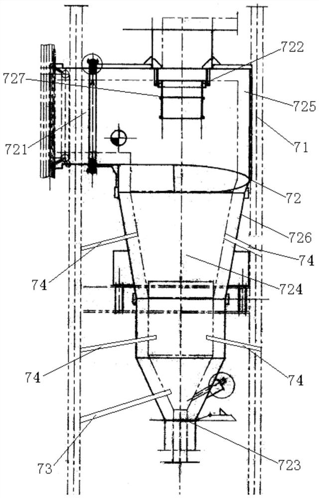
[0024] refer to figure 1 , a preferred embodiment of the present invention provides a flue gas separation device, comprising: a mounting frame 71 supported on the ground, and a flue gas separator 72 for separating the flue gas is supported on the mounting frame 71, the flue gas separation The device 72 is provided with a flue gas inlet 721 for the flue gas to be separated to enter, a flue gas outlet 722 for the separated fine particle flue gas to enter downstream processing, and a flue gas outlet 722 for the separated coarse particle flue gas to return to the circulating fluidized bed The flue gas outlet 723. Mounting frame 71 is also supported with shock wave air cannon 73, and the firing end of shock wave air cannon 73 is communicated with the flue gas passage ...


PUM


Abstract

The invention discloses a flue gas separation device. The flue gas separation device comprises a mounting frame; a flue gas separator is arranged on the mounting frame in a supporting mode; a flue gasinlet allowing flue gas to be separated to enter the flue gas separator, a flue gas outlet allowing separated fine particle flue gas to enter downstream treatment and a flue gas exhaust port allowingseparated coarse particle flue gas to return to a circulating fluidized bed again are formed in the flue gas separator; a shock wave air cannon is further arranged on the mounting frame in a supporting mode; the blasting end of the shock wave air cannon communicates with a flue gas channel of the flue gas separator; and the shock wave air cannon is used for discharging instant air shock waves tothe flue gas channel according to a set frequency so as to crush bonded ash blocks hardened on the wall of the flue gas channel into return ash, and then the return ash is discharged into the circulating fluidized bed through the flue gas exhaust port. In the flue gas separation device, the instantaneous air shock waves can also effectively prevent flue gas from hardening on the wall of the flue gas channel during separation, so that less bonded ash blocks are formed, flue gas is smoothly discharged from the flue gas channel, the amount of return ash returned to a hearth is increased, and a boiler is stable in combustion.

Description

technical field [0001] The invention relates to the technical field of biomass generator sets, in particular to a flue gas separation device. Background technique [0002] In the biomass generator set, the furnace is connected with a flue, and the flue gas produced by the combustion of biomass fuel in the furnace enters the flue, and then enters the separation device through the flue, and the flue gas is separated under the action of the separation device. The flue gas of the particles continues to move forward after exiting the separation device, and enters the inertial separator and / or bag filter system installed downstream, while the flue gas of the coarser particles falls into the flue gas separator, and then is separated by the flue gas The device enters the return material bed, and returns to the furnace for combustion under the action of the circulating return material of the return material bed. [0003] Since the flue gas contains silicon dioxide, it is easy to for...

Claims


Application Information

Patent Timeline
Patent Type & Authority Applications(China)
IPC IPC(8): F23C10/24F23C10/26F23C10/20F23C10/28
CPCF23C10/24F23C10/26F23C10/20F23C10/28Y02A50/2351
Inventor 王熙毅王热华贾星亮贾奥万为华王熙福蔡爱年
Owner 安化华晟生物能源有限责任公司
Why Eureka
Try Eureka