Slag remover
A technology of slag removal machine and machine body, which is applied in the field of chain boilers, can solve the problems of chain furnaces such as easy coking, frequent maintenance, and burning motors, so as to eliminate the phenomenon of burning motors, reduce the number of shutdowns, and improve the service life.
Inactive Publication Date: 2013-04-03
大连锅炉集团有限公司
View PDF0 Cites 0 Cited by
- Summary
- Abstract
- Description
- Claims
- Application Information
AI Technical Summary
Problems solved by technology
[0002] In the prior art, the slag remover relies on the reciprocating movement of the slag pushing plate to push the ash from the outlet and fall into the box of the chain plate slag remover below. This structure is not suitable for the chain furnace because it is easy to coke and run out of fire. , resulting in burnout and deformation of the slag pushing plate, ground leakage of the bottom plate, slag discharge blockage, frequent daily maintenance, seriously affecting production, and the phenomenon of burning motors
Method used
View moreImage
Smart ImageViewing Examples

Examples
Embodiment Construction
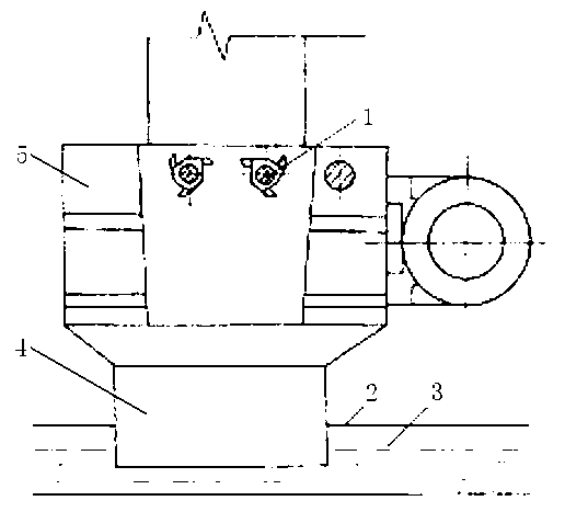
[0008] Such as figure 1 As shown, the slag removal machine includes a chain plate machine box body 2, a water seal 3 and a body 5. A slag breaker 1 is installed on the body 5, and an ash drop port 4 is installed on the bottom of the body 5. The chain plate machine case The inside of the body 2 is provided with a water seal 3, and the ash drop port 4 is placed in the water seal 3, so that the ash and slag directly fall into the water.
Login to View More PUM
 Abstract
The invention discloses a slag remover which comprises a chain-slat conveyer box body, a water seal and a remover body, wherein a slag crusher is mounted on the remover body; a dust falling port is formed in the lower part of the remover body; the water seal is arranged inside the chain-slat conveyer box body; and the dust falling port is formed in the water seal. The slag remover has the advantages that the faults are relatively reduced, the maintenance intensity is reduced, the shutdown frequency is reduced, the load of a motor is reduced, the phenomenon of motor burning is basically eliminated, the dust removal speed is increased, and the service life is prolonged.
Description
technical field [0001] The invention relates to the technical field of chain boilers, in particular to a slag remover. Background technique [0002] In the prior art, the slag remover relies on the reciprocating movement of the slag pushing plate to push the ash from the outlet and fall into the box of the chain plate slag remover below. This structure is not suitable for the chain furnace because it is easy to coke and run out of fire. , resulting in burnout and deformation of the slag pushing plate, floor grinding leakage, slag discharge blockage, and frequent daily maintenance, which seriously affects production, and at the same time, the phenomenon of motor burning occurs. Contents of the invention [0003] The object of the present invention is to overcome the above-mentioned deficiencies and provide a slag remover. [0004] The technical solution adopted by the present invention to achieve the above object is: a slag remover, including a chain plate machine box body...
Claims
Login to View More Application Information
Patent Timeline
 Patent Type & Authority Applications(China)
IPC IPC(8): F23J1/06
Inventor 闫其林曲胜财
Owner 大连锅炉集团有限公司
Features
- R&D
- Intellectual Property
- Life Sciences
- Materials
- Tech Scout
- Unparalleled Data Quality
- Higher Quality Content
- 60% Fewer Hallucinations
Learn More Browse by: Latest US Patents, China's latest patents, Technical Efficacy Thesaurus, Application Domain, Technology Topic, Popular Technical Reports.
© 2025 PatSnap. All rights reserved.Legal|Privacy policy|Modern Slavery Act Transparency Statement|Sitemap|About US| Contact US: help@patsnap.com