Heat accumulation type rapid pyrolysis furnace with wear-resisting radiation tubes

A radiant tube and pyrolysis furnace technology, applied in the field of coal chemical industry, can solve the problems of weakening wear, affecting the normal operation and wear of the device, and achieving the effect of prolonging the service life, reducing the maintenance cost of the pyrolysis furnace, and prolonging the operation period.

Pending Publication Date: 2018-04-20
北京恒丰亚业科技发展有限公司
View PDF6 Cites 0 Cited by
  • Summary
  • Abstract
  • Description
  • Claims
  • Application Information

AI Technical Summary

Problems solved by technology

Although the above methods have certain effects, none of them can fundamentally weaken the wear and have an anti-wear effect. When the device has been in operation for a period of time, wear behavior will still occur, affecting the normal operation of the device

Method used


Image

  • Heat accumulation type rapid pyrolysis furnace with wear-resisting radiation tubes
  • Heat accumulation type rapid pyrolysis furnace with wear-resisting radiation tubes

Examples


Embodiment 1

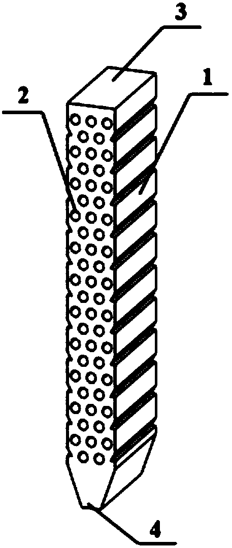
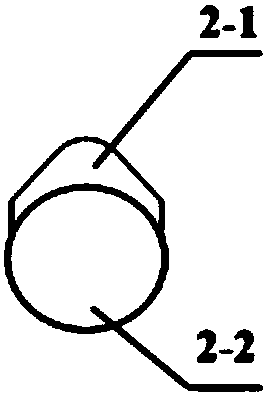
[0034] The oval cap is welded on the radiant tube through a rectangular sheet, and the radiant tube is set in the vertical square pyrolysis furnace, so that the horizontal and vertical distances between the two radiant tubes are the same. in:

[0035] The vertical square regenerative rapid pyrolysis furnace is 12 m high, the top is a rectangle of 1.4*3.0 m, the bottom is a rectangle of 0.5*3 m, and 55 radiant tubes are arranged inside, with a total of 22 layers; the The diameter of the radiant tubes in the vertical square regenerative rapid pyrolysis furnace is 200 mm, and the horizontal and vertical spacing of the radiant tubes are 410 mm respectively; the particle size distribution of pulverized coal in the vertical square regenerative pyrolysis furnace is wide. , the particle size range is concentrated between 0.18-3 mm, and about 50% of the particles are between 1-2 mm; the vertical distance from the top of the cap to the center of the radiant tube is 200 mm, and the thickne...

Embodiment 2

[0037] The oval cap is welded on the radiant tube through the rectangular sheet, and the radiant tube is set in the vertical cylindrical pyrolysis furnace, so that the horizontal and vertical distances between the two radiant tubes are the same. in:

[0038] The vertical cylindrical regenerative rapid pyrolysis furnace is 30 m high and 30 m in diameter, and 100 radiant tubes are arranged inside, with a total of 10 layers; the diameter of the radiant tubes in the pyrolysis furnace is 200 mm, and the radiation The horizontal and vertical spacing between the two tubes is 410 mm respectively; the particle size distribution of pulverized coal in the vertical cylindrical regenerative pyrolysis furnace is wide, and the particle size range is concentrated between 0.18 and 3 mm, and about 50% The particle size is between 1 and 2 mm; the vertical distance from the top of the cap to the center of the radiant tube is 300 mm, the thickness of the cap is 4 mm, and the length of the cap is 2...


PUM

PropertyMeasurementUnit
diameteraaaaaaaaaa
thicknessaaaaaaaaaa
lengthaaaaaaaaaa

Abstract

The invention relates to a heat accumulation type rapid pyrolysis furnace with wear-resisting radiation tubes. The heat accumulation type rapid pyrolysis furnace comprises a pipe cap, a mounting partand the radiation tubes, wherein the horizontal and vertical distances between each two radiation tubes arranged in the pyrolysis furnace are the same; the pipe cap is an arc-shaped plate with an ovalcross section; the mounting part is arranged on the radiation tubes; the arc-shaped plate is arranged on the mounting part so that the pipe cap is located above the radiation tubes, and a condition that the radiation tubes are directly impacted by materials is avoided. According to the heat accumulation type rapid pyrolysis furnace provided by the invention, a condition that tube walls of the radiation tubes are directly washed is avoided, so that the radiation tubes are not damaged and abraded and the service life of the radiation tubes is prolonged; the overhauling cost of the pyrolysis furnace is reduced, and the number of times of blowing down the pyrolysis furnace in an operation process is reduced; the potential safety hazards and the economic loss, caused by abrasion of the radiation tubes, are reduced; safe and normal operation of the heat accumulation type rapid pyrolysis furnace is ensured and the operation cycle of the pyrolysis furnace is prolonged.

Description

technical field [0001] The invention belongs to the technical field of coal chemical industry, and in particular relates to a regenerative rapid pyrolysis furnace with anti-wear radiant tubes. Background technique [0002] Coal pyrolysis is the initial stage of coal processing, conversion and utilization processes such as coal gasification, liquefaction and combustion, and is also an extremely important intermediate process. At present, the existing technology is based on the regenerative high-temperature air combustion technology, and the rapid pyrolysis furnace is used to extract artificial oil and artificial natural gas resources from low-rank coal raw materials such as lignite and long-flame coal, which can not only fill the gap of my country's oil and natural gas resources, but also It can solve the world problem of low-rank coal physique and resource utilization. However, during the long-term operation of the pyrolysis furnace, the violent downward movement of the pulv...

Claims


Application Information

Patent Timeline
Patent Type & Authority Applications(China)
IPC IPC(8): C10B53/04C10B47/18
CPCC10B47/18C10B53/04
Inventor 彭丽孟嘉乐郑倩倩张宏伟窦从从肖磊吴道洪
Owner 北京恒丰亚业科技发展有限公司
Why Eureka
Try Eureka