
Automatic tool changing system of sleeve joint type numerical control machine tool

A technology of automatic tool change and CNC machine tools, applied in the directions of metal processing machinery parts, clamping, support, etc., can solve the problems of endangering the personal safety of operators, imperfect automatic tool changing system of machine tools, difficult to observe tools, etc., and achieve waste. The effect of machining time, simple structure, tool change efficiency and precision improvement

Inactive Publication Date: 2021-02-26
马鞍山绿准数控科技有限公司
View PDF4 Cites 0 Cited by
  • Summary
  • Abstract
  • Description
  • Claims
  • Application Information

AI Technical Summary

Problems solved by technology

Especially when the CNC equipment is in a semi-closed state, it is difficult for the operator outside the equipment to observe the state of the tool. If the tool breaks during the processing of the equipment, it will even endanger the personal safety of the operator. The automatic tool change system of the machine tool is not perfect

Method used


Image

  • Automatic tool changing system of sleeve joint type numerical control machine tool
  • Automatic tool changing system of sleeve joint type numerical control machine tool
  • Automatic tool changing system of sleeve joint type numerical control machine tool

Examples


Embodiment

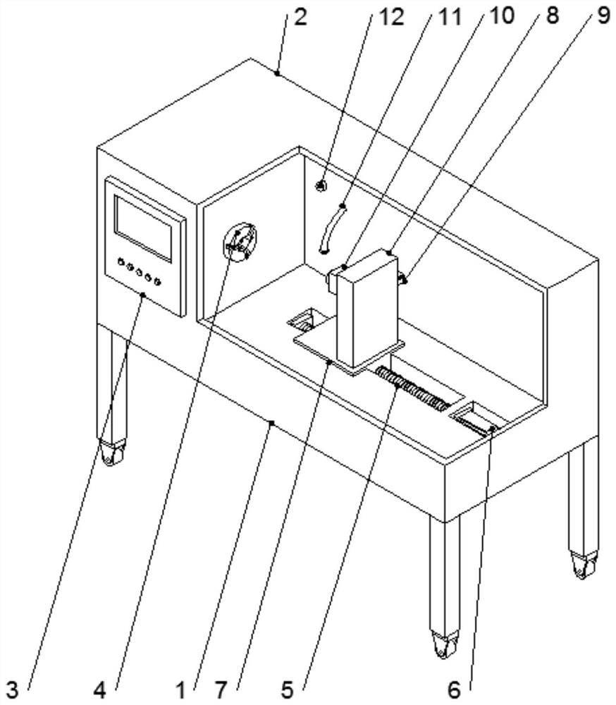
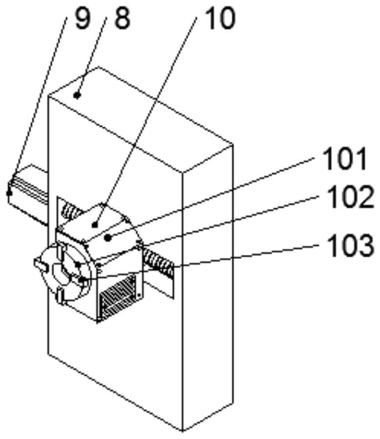
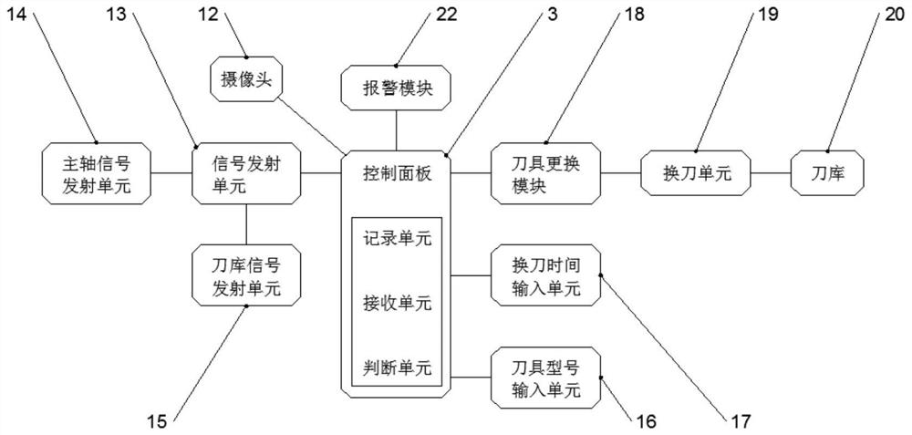
[0018] Example: such as Figure 1-3 As shown, the present invention is an automatic tool change system for socket-type CNC machine tools, which includes a table 1, a housing 2 and an automatic tool change mechanism 10. The four corners of the bottom end of the table 1 are fixedly connected with outriggers, and the bottom ends of the outriggers are fixedly connected There are rollers, the top of the platen 1 is fixedly connected with the shell 2, the front end of the shell 2 is fixedly connected with the control panel 3, the inner surface of the shell 2 is fixedly connected with the three-jaw chuck 4, and the top of the platen 1 is provided with a first groove , the first ball screw 5 is arranged inside the first groove, and the second groove is arranged on the top of the platen 1 . A first motor 6 is arranged inside the second groove, and the output shaft of the first motor 6 is connected to the first ball screw 5 by transmission. The surface of the first ball screw 5 is screw...


PUM


Abstract

The invention provides an automatic tool changing system of a sleeve joint type numerical control machine tool. The automatic tool changing system comprises a platen, a shell and an automatic tool changing mechanism, supporting legs are fixedly connected to the four corners of the bottom end of the platen, rolling wheels are fixedly connected to the bottom ends of the supporting legs, the shell isfixedly connected to the top end of the platen, a control panel is fixedly connected to the front end face of the shell, a three-jaw chuck is fixedly connected to one surface of the inner side of theshell, a first groove is formed in the top of the platen, a first ball screw is arranged in the first groove, and a second groove is formed in the top of the platen; and a first motor is arranged inthe second groove, an output shaft of the first motor is in transmission connection with a first ball screw, the surface of the first ball screw is in threaded connection with a first sliding block, the top end of the first sliding block is fixedly connected with a rack, and a third groove is formed in the side, close to the three-jaw chuck, of the rack. The automatic tool changing system is simple and reasonable in structure and novel in design, and has high efficiency in the aspect of automatic tool changing systems of sleeve joint type numerical control machine tools.

Description

technical field [0001] The invention relates to the technical field of an automatic tool change system for a socket-type numerical control machine tool, in particular to an automatic tool-change system for a socket-type numerical control machine tool. Background technique [0002] In the application process of CNC machine tools, various tools are often involved. During the specific use of the tool, depending on the use environment, use parameters, and use time, the tool will be worn to varying degrees, and the wear of the tool , will directly affect the precision of machining, the efficiency of machining and the economic benefits of enterprises. Especially when the CNC equipment is in a semi-closed state, it is difficult for the operator outside the equipment to observe the state of the tool. If the tool breaks during the processing of the equipment, it will even endanger the personal safety of the operator. The automatic tool change system of the machine tool is not perfect...

Claims


Application Information

Patent Timeline
Patent Type & Authority Applications(China)
IPC IPC(8): B23Q3/155B23Q17/09B23Q11/00
CPCB23Q3/155B23Q11/0089B23Q17/0952
Inventor 陈聪友
Owner 马鞍山绿准数控科技有限公司
Learn More