Optimized crystallization heat preservation furnace

A holding furnace and crystallization technology, which is applied in the direction of furnaces, crucible furnaces, furnace components, etc., can solve the problems of casting furnace cracking, high power consumption, sticking aluminum and slag, etc., and achieves short service life, good heat preservation effect, and improved oxidation. Effect

Inactive Publication Date: 2021-02-23
边仁杰
View PDF2 Cites 0 Cited by
  • Summary
  • Abstract
  • Description
  • Claims
  • Application Information

AI Technical Summary

Problems solved by technology

[0005] The disadvantages of the existing die-casting furnaces are: a. The baking time of the new furnace is too long to go online for more than 20 days; b. The pouring furnace is 100% cracked and the life is short for 3-5 years; c. The die-casting furnace is also used to be called a holding furnace. However, the holding furnace does not need to be equipped with a 36 kWh heater, which consumes a lot of electricity and is a big tiger group of electricity. d. The lining material of the poured die-casting furnace or the holding furnace sticks to aluminum and slag, and the aluminum slag is cleaned. The furnace hall is very hard. If this problem is not solved, there will be obstacles for die-casting to enter the 5G Internet of Things era. e. The cast-molded die-casting furnace or holding furnace is equipped with a 36 kWh heater. It is difficult to maintain a constant temperature in the range of 700±5°C. f .The temperature of the space above the liquid surface of aluminum water is high, and the oxidation l

Method used


Image

  • Optimized crystallization heat preservation furnace
  • Optimized crystallization heat preservation furnace
  • Optimized crystallization heat preservation furnace

Examples


Embodiment Construction

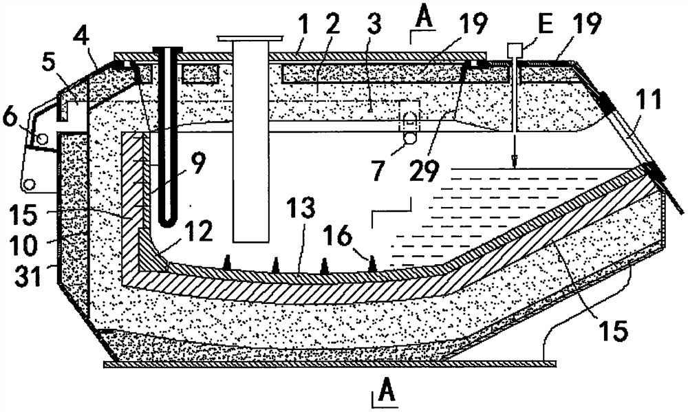
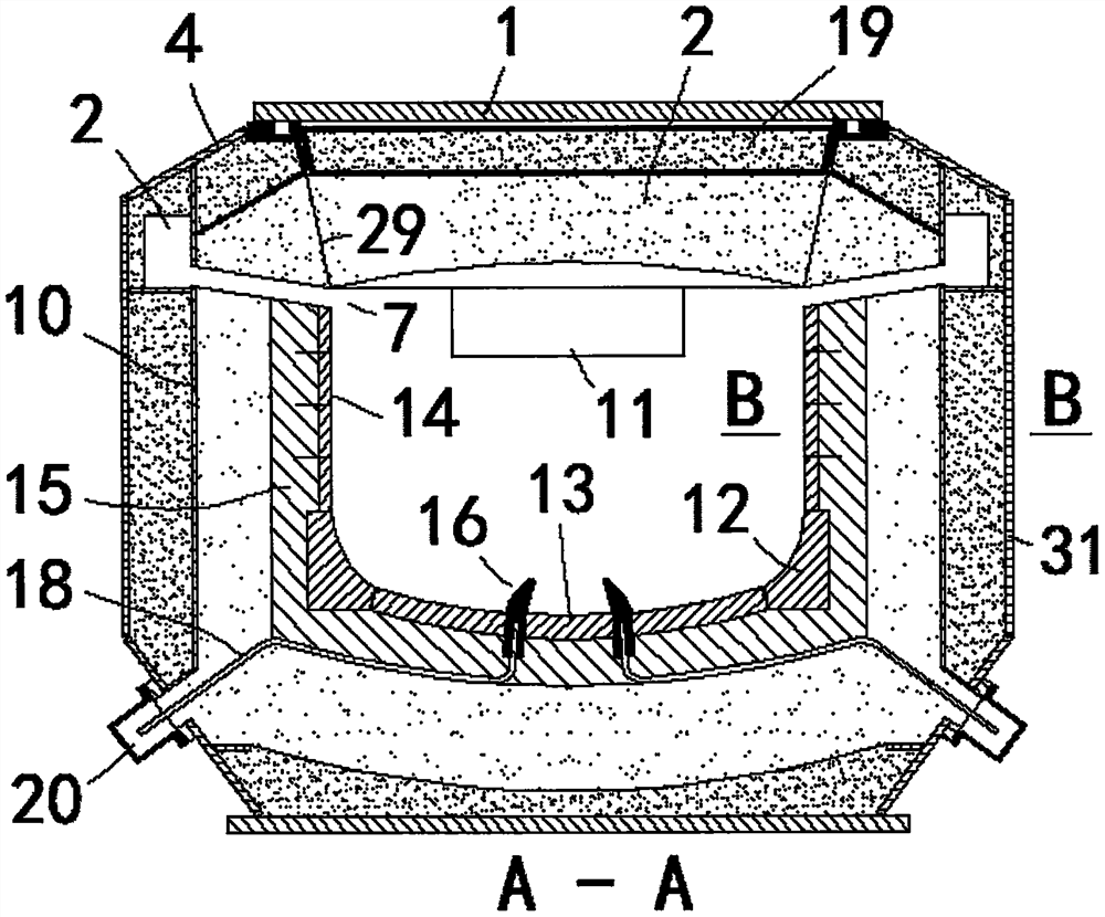
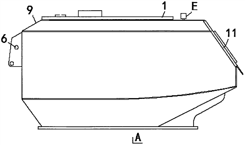
[0058] The utility model is described further with reference to accompanying drawing now.

[0059] attached Figure 1-15 What is shown is the general concept of the invention.

[0060] Figure 1-5 As shown, the inner side of the furnace shell wall is provided with an inner tank wall with a shape of a curved line in a top view. The inner tank wall is formed by tangentially connecting the semi-circular arc plates 10 with the circular arc plates 17 on both sides, and the circular arc plates 17 on both sides are in phase The curved liner wall formed by cutting the semi-circular arc plate 10 is connected to the furnace mouth plate. Bolts on the body part 4 are sealed and connected to the furnace cover plate 1, and the furnace roof plate between the furnace cover plate 1 and the furnace mouth plate is provided with a laser rangefinder E, which irradiates the aluminum liquid surface at set intervals , to measure the distance of the liquid level change, the variable value of the di...


PUM

PropertyMeasurementUnit
Diameteraaaaaaaaaa

Abstract

The invention relates to an optimized crystallization heat preservation furnace, and relates to heat preservation and optimized casting microstructure. The optimized crystallization heat preservationfurnace is characterized in that a soft heat preservation pouring material and a hollow ball are used as a main body heat preservation furnace wall, a zirconium armor brick is anchored on the inner wall of the main body heat preservation furnace wall to be used as a non-stick aluminum lining layer, and the zirconium armor brick belongs to a permanent ultra-long service life die-casting furnace lining material. Therefore, the novel heat preservation furnace not only possesses better heat preservation performance, but also possesses an extraordinary service life, and is a heat preservation furnace which is not sticky to aluminum. On the basis of the advantages of being good in heat preservation, long in service life and non-sticky to aluminum, the optimized crystallization heat preservationfurnace is additionally provided with the molten aluminum self-resistance thermode, electric energy is converted into heat energy through the self-resistivity of molten aluminum, and therefore, the energy utilization efficiency is high, and the structure of the furnace body is very simple; the resistance thermode is also an electric pulse throwing electronic device, thrown electrons are beneficialto manufacturing a casting body with a finer microstructure through pressure casting, and therefore, the surface quality pass percent of a casting hub can be increased, and the mechanical performancecan be obviously improved.

Description

technical field [0001] The invention relates to heat preservation and optimization of casting microstructure, especially microstructure of heat preservation furnace and wheel hub for die casting. Background technique [0002] There is an application number: 2019102354107, which is called a patent application for "high-temperature shock-absorbing insulation block", and another application number: 201910396404. Material" thermal insulation refractory material, the thermal insulation refractory material named "soft thermal insulation castable material" is based on the material selection and ingredients of the "elastic block" material described in the patent number: 201510564465.4 furnace door flexible sealing ring device, preferably A kind of material processed by less water or no water pouring process, a kind of soft thermal insulation refractory material with certain plasticity and resilience. The material has achieved very ideal thermal insulation effect in an industrial exp...

Claims


Application Information

Patent Timeline
IPC IPC(8): F27B14/06F27B14/14F27B14/20F27D1/04B22D41/02B22D41/01B22D1/00
CPCB22D1/00B22D41/01B22D41/02F27B14/06F27B14/14F27B14/20F27D1/042
Inventor 杨兴张宝袁必辉孙永泽卜哲岩陆志强马春刚史国飞边仁杰
Owner 边仁杰
Why Eureka
Try Eureka