Novel textile steel wire ring molding machine tool

A traveler and textile technology, applied in the field of new textile traveler forming machine tools, can solve problems such as low processing efficiency and complex structure, achieve the effects of improving forming accuracy, improving equipment flexibility, and avoiding the reduction of forming accuracy

Active Publication Date: 2021-02-23
XI'AN POLYTECHNIC UNIVERSITY
View PDF6 Cites 0 Cited by
  • Summary
  • Abstract
  • Description
  • Claims
  • Application Information

AI Technical Summary

Problems solved by technology

[0004] The purpose of the present invention is to provide a new type of textile traveler forming machine tool, which solves the problem of complex structure of the existing traveler forming machine tool, and the low processing efficiency of the equipment due to the drive of each unit by compact cam row transmission.

Method used


Image

  • Novel textile steel wire ring molding machine tool
  • Novel textile steel wire ring molding machine tool
  • Novel textile steel wire ring molding machine tool

Examples


Embodiment Construction

[0035] The present invention will be described in detail below in conjunction with the accompanying drawings and specific embodiments.

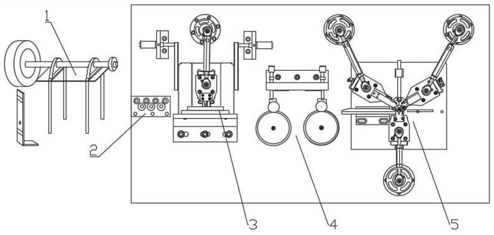
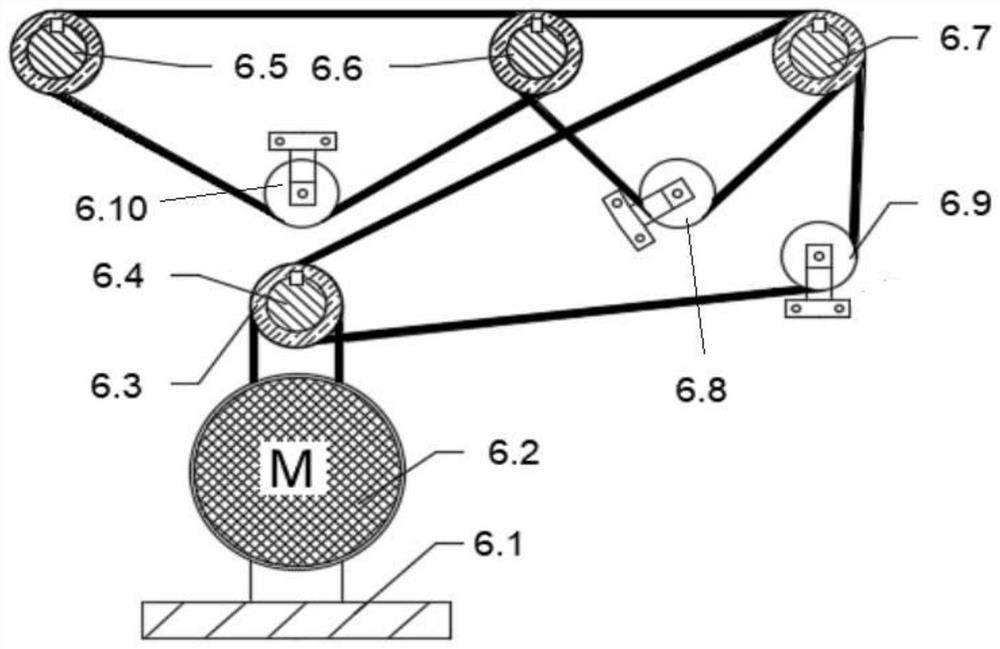
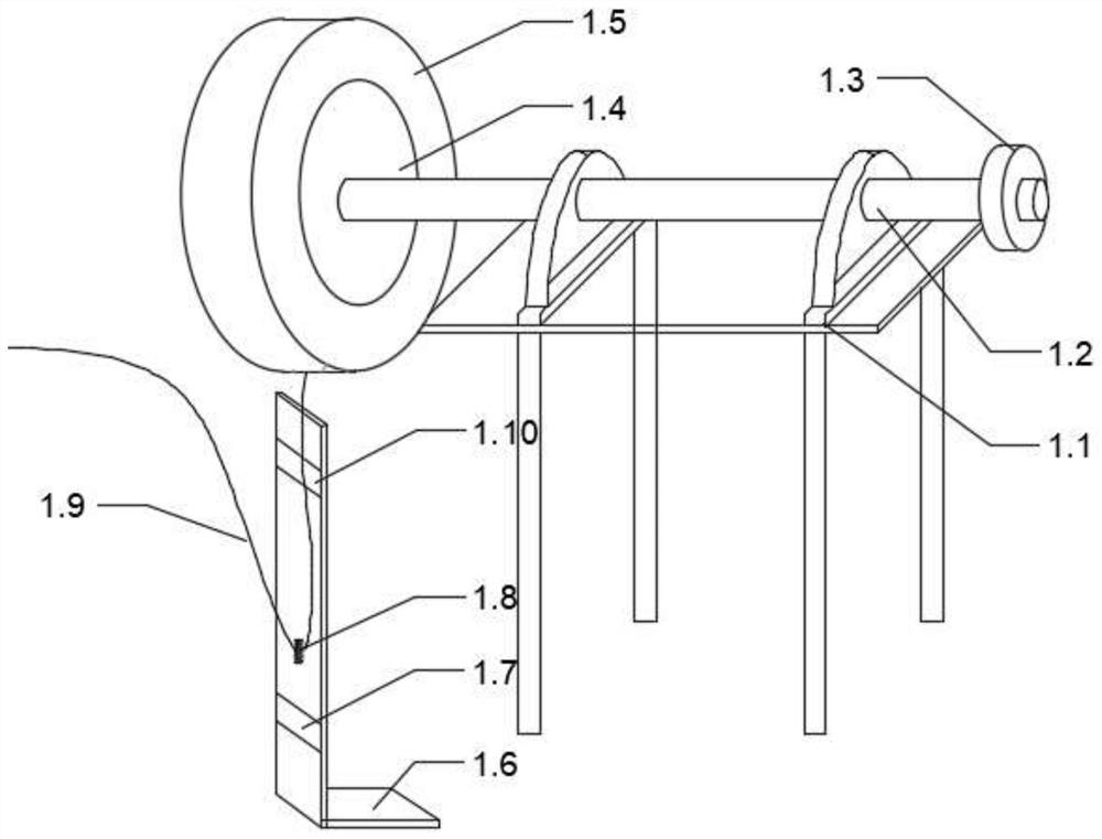
[0036] Such as figure 1 , the traveler forming machine tool of the present invention is sequentially provided with a feeding unit 1, a straightening unit 2, a window unit 3, a wire feeding unit 4, a forming unit 5 and a material returning unit according to the feeding route (because the returning unit is located in the forming unit 5 on the back, so the figure 1 The material return unit is not drawn in ); among them, the discharge unit 1 is driven by the discharge motor, which is a single-input single-output driving mode; the wire feeding unit 4 is driven by a wire-feeding motor, which is a single-input single-output driving mode; the window opening unit 3 , the molding unit 5 and the stripping unit are uniformly driven by the molding motor 6.2 (called an asynchronous motor), which is a single-input multi-output drive mode, see figure 2 . ...


PUM


Abstract

The invention discloses a novel textile steel wire molding machine tool. The novel textile steel wire molding machine tool sequentially comprises a discharge unit, a straightening unit, a window opening unit, a wire feeding unit, a molding unit and a material return unit, wherein the discharge unit comprises a discharge shaft mounted on a bracket, one end of the discharge shaft is fixedly providedwith a synchronous belt wheel V in a sleeving mode; the synchronous belt wheel V is in drive connection to the discharge motor through a fifth synchronous belt; the other end of the discharge shaft is fixedly provided with an inner expansion type discharge wheel in the sleeving mode; a flat wire material tray sleeves the outer periphery of the inner expansion type discharge wheel; a sensor mounting base is arranged below the inner expansion type discharge wheel; an upper limiting sensor and a lower limiting sensor are mounted on a vertical plate of the sensor mounting base in a spaced mode; and a counterweight ring sleeves a flat wire fed out from the flat wire material tray. Through an automatic control system and an automatic structural design, the device is remarkably improved in degree of automation, and is improved in equipment flexibility and molding precision.

Description

technical field [0001] The invention belongs to the technical field of textile machinery and relates to a novel textile traveler forming machine tool. Background technique [0002] At present, the traveler forming machines commonly used by domestic traveler manufacturers are mainly vertical and compact transmission modes, including a feeding unit, a leveling unit, a wire feeding unit, a window opening unit, a forming unit and a material returning unit. During the working process, the flat wire is clamped by the clamping unit and dragged forward. During the dragging and feeding process, the flat wire tray rotates to discharge. This passive discharging method will cause the flat wire to elongate. The fenestration unit punches the fenestration with a punching needle. After the flat wire is cut, the traveler is formed by two bendings. Finally, the core mold retreats, and under the action of the baffle, the processed steel traveler exits the core mold forming position. [0003...

Claims


Application Information

Patent Timeline
Patent Type & Authority Applications(China)
IPC IPC(8): B21F37/00B21F23/00B21F1/00B21F11/00B21F1/02
CPCB21F37/00B21F23/00B21F1/00B21F11/00B21F1/026
Inventor 王俊勃孙国梁马榛姜凤阳雒千卫晋波李锦波代阿瑞张小峰
Owner XI'AN POLYTECHNIC UNIVERSITY
Why Eureka
Try Eureka