


Quick Research
Generate reliable direction feasibility study reports for your R&D in just a few steps.

Technical Q&A
Discover and master advanced knowledge NOW. Basics, ideas, possibilities, all at once.

Find Solutions
As an expert in R&D theories, this can generate solutions to your technical problems instantly.

Evaluate Feasibility
Analyze your overall solution with one click, know your potential R&D risks in advance.

Monitor Landscape
Get weekly tech updates, stay abreast of the latest tech innovations and key insights.
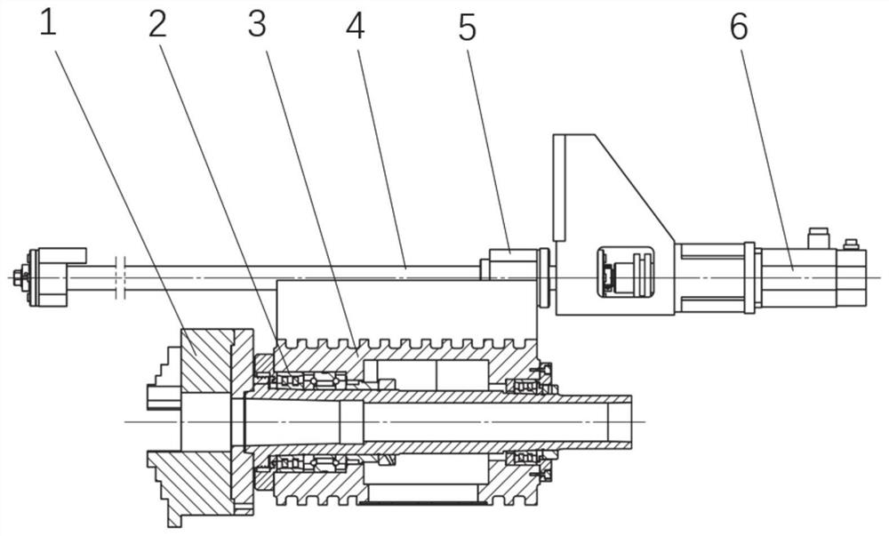
Workpiece clamping device, machine tool and method for laser cladding
A technology of laser cladding and workpiece clamping, applied in metal material coating process, coating and other directions, can solve problems such as workpiece axial deformation, and achieve the effect of eliminating machining vibration, ensuring production safety, and reducing machining defects.
- Summary
- Abstract
- Description
- Claims
- Application Information
AI Technical Summary
Problems solved by technology
Method used
Image

Examples
Embodiment 2
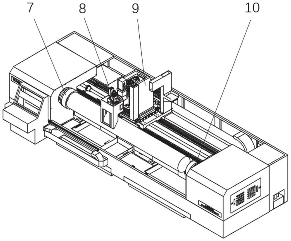
[0037] This embodiment discloses a laser cladding machine tool, such as Figure 2-Figure 3 As shown, the workpiece clamping device for the laser cladding machine tool described in Embodiment 1 is installed, the main shaft of the laser cladding machine tool is connected to the first fixing member 7, and the tailstock is installed on the laser cladding machine tool On the tail sub-spindle 10 of the body, both the tailstock and the sub-spindle are slidingly connected with the bed, and the laser cladding machine tool also includes a three-axis moving table 9 and a laser cladding head 8 installed thereon, as well as electric control, communication Lines and peripheral equipment such as cooling, dust removal, powder feeding, and protection. The above-mentioned equipment is the terminal and body for processing, which determines the stability and safety of the processing process and the final quality of the processed workpiece. The existing structure and scheme can be used. Its specif...
Embodiment 3
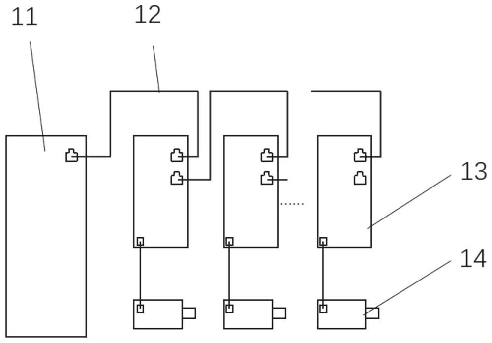
[0049] This embodiment discloses a working method of the laser cladding machine tool described in Embodiment 2:
[0050] Such as Figure 4 As shown, in the processing process, the main control system of the laser cladding machine tool calculates the constant torque required by the sub-spindle in advance according to the geometric parameters and material parameters of the workpiece, and sends this torque command to the sub-spindle servo motor, and interpolates at the same time Calculate and issue the position or speed commands of the servo motors connected to other axes, and each servo motor will act according to the commands. The tailstock applies a set axial load to the workpiece through the second fixture, and the main control system periodically sends a constant torque command to the sub-spindle servo motor through the bus, and the sub-spindle servo motor responds to the command to achieve constant axial force control .
[0051] The first fixing part rotates under the dri...
PUM
 Abstract
Description
Claims
Application Information
 - R&D Engineer
- R&D Manager
- IP Professional
- Industry Leading Data Capabilities
- Powerful AI technology
- Patent DNA Extraction
Browse by: Latest US Patents, China's latest patents, Technical Efficacy Thesaurus, Application Domain, Technology Topic, Popular Technical Reports.
© 2024 PatSnap. All rights reserved.Legal|Privacy policy|Modern Slavery Act Transparency Statement|Sitemap|About US| Contact US: help@patsnap.com