
Lifting device used for building prefabricated slabs

A hoisting device and prefabricated board technology, which is applied in the direction of lifting equipment braking device, hoisting device, transportation and packaging, etc., can solve the problems of easy cracking of building materials, poor earthquake resistance, complex structure of advanced shock absorption equipment, etc.

Inactive Publication Date: 2021-02-19
陈平英
View PDF1 Cites 2 Cited by
  • Summary
  • Abstract
  • Description
  • Claims
  • Application Information

AI Technical Summary

Problems solved by technology

[0002] On the construction site, it is often necessary to lift building materials or prefabricated panels from the ground to high places, and the lifting frames and hooks used for lifting are often unable to be fixed with the building prefabricated panels and panel materials, and it is impossible to lift buildings driven by motors Precast panels and panel materials
[0003] The existing construction lifting frame design is relatively traditional, and its anti-seismic ability is poor, which makes it easy to be cracked when lifting heavy building materials, and due to the heavy weight of the plate and strong inertia, the ropes often break due to inertia
The advanced shock absorbing equipment is not only too complicated in structure and high in cost, but also easy to damage and not strong in applicability. Moreover, when it is tied with ropes and hoisted with hooks, it will also fall off due to the uneven center of gravity of the board.
[0004] Chinese patent (publication number: CN211712419U) discloses a lifting frame for building prefabricated panels, including a fixed column and a lifting column, a first groove is opened in the center of the fixed column, and the first groove A first bearing is fixed inside, the inner wall of the first bearing is welded to the lower end of the lifting column, the top surface of the lifting column is welded with a lifting ring, and the two ends of the fixing column are located in the first groove Second bearings are welded on both sides, the inner walls of the two second bearings are welded to the fixing column, and the outer walls of the two second bearings are welded with fixing blocks, and the two fixing blocks run through the interior of the upper end and the second bearing. The outer wall of the bearing is welded, and the lower ends of the two fixed blocks are fixedly provided with mounting plates. Although this device can achieve the stability of lifting and transporting the building prefabricated panels to a certain extent, in actual operation, the device cannot Precast slabs perform efficient hoisting movements, therefore, further improvements are required

Method used


Image

  • Lifting device used for building prefabricated slabs
  • Lifting device used for building prefabricated slabs
  • Lifting device used for building prefabricated slabs

Examples


Embodiment 1

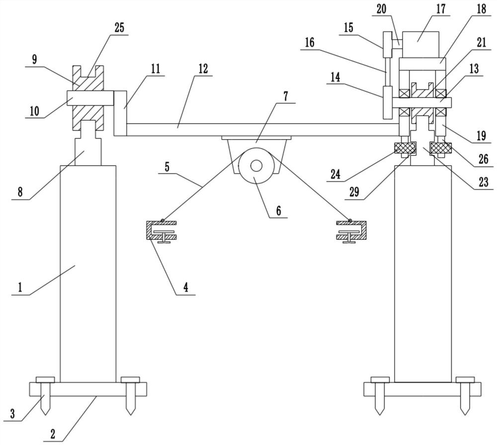
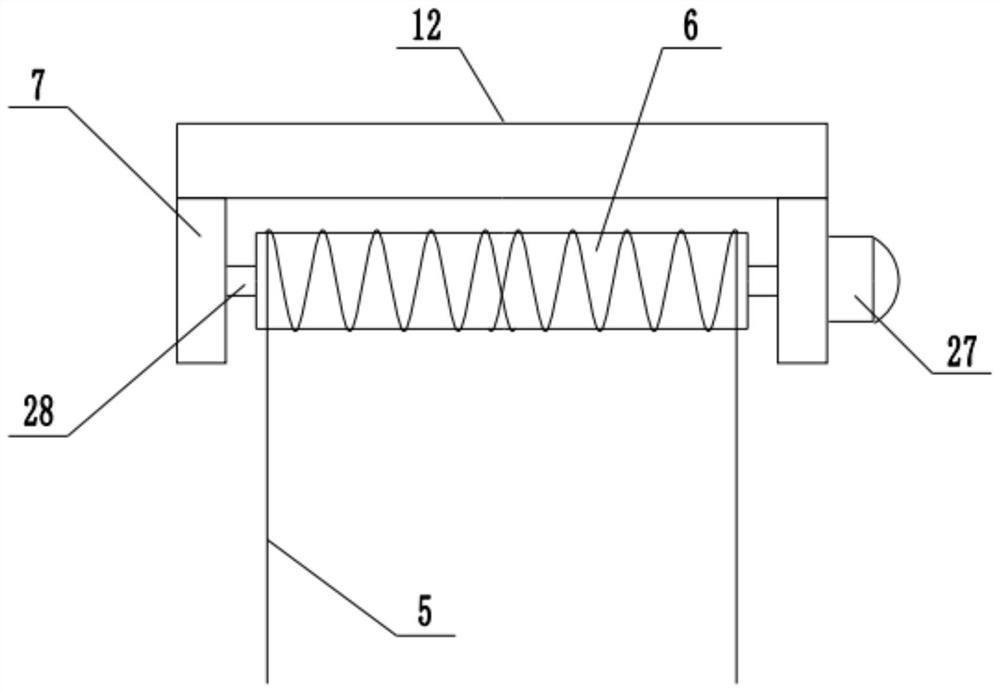
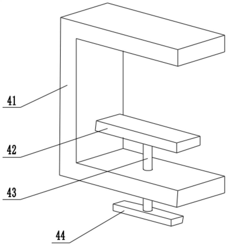
[0028] refer to Figure 1~3 , in an embodiment of the present invention, a lifting device for building prefabricated panels includes a fixed base plate 2, and fixing bolts 3 are installed on both sides of the lower end of the fixed base plate 2 to realize the fixed installation of the entire fixed base plate 2, and the fixed base plate 2 The upper end of the fixed column 1 is installed, and the left rail 8 is installed on the upper end of the left fixed column 1. The upper end of the left rail 8 is rotated and provided with a left roller 9. The left roller 9 is installed with a guide column 10 through a bearing, and the middle of the left roller 9 is rotated. There is a guide column 10, and a right rail 23 is installed on the upper end of the right fixed column 1, and a balance groove 29 cooperating with a balance wheel 24 is provided on both sides of the right rail 23, and is used to limit and guide the forward and backward movement of the walking frame 19. Avoid left and rig...

Embodiment 2

[0030]In another embodiment of the present invention, a fixed base plate 2 is included, fixing bolts 3 are installed on both sides of the lower end of the fixed base plate 2, a fixed column 1 is installed on the upper end of the fixed base plate 2, and a left rail 8 is installed on the upper end of the left fixed column 1. 8. The upper end of the left roller 9 is rotated to be provided with a left roller 9, and the guide column 10 is mounted on the left roller 9 through a bearing, and the middle part of the left roller 9 is rotated to be provided with a guide column 10. 23 both sides are provided with the balance groove 29 that cooperates mutually with balance wheel 24, and the upper end of right track 23 is rotated and is provided with right roller 21, and the middle part of right roller 21 is fixedly installed with rotating shaft 13, and the two ends of rotating shaft 13 are installed walking frame through bearing 19. The balance column 26 is installed at the bottom of the wa...


PUM


Abstract

The invention relates to the technical field of building construction, and discloses a lifting device used for building prefabricated slabs. The lifting device comprises a fixed bottom plate, fixed columns are mounted at the upper end of the fixed bottom plate, a left rail is mounted at the upper end of the fixed column on the left side, a left rolling wheel is rotatably arranged at the upper endof the left rail, and a guide column is rotatably arranged in the middle of the left rolling wheel. A right rail is mounted at the upper end of the fixed column on the right side, a right rolling wheel is rotatably arranged at the upper end of the right rail, a rotating shaft is fixedly installed in the middle of the right rolling wheel, walking frames are installed at the two ends of the rotatingshaft through bearings, a motor plate is installed at the upper ends of the walking frames, a rotating motor is installed at the upper end of the motor plate, an output shaft of the rotating motor isconnected with a driving belt wheel, and the lower end of the driving belt wheel is connected with a driven belt wheel through a belt. According to the lifting device, lifting operation to the building prefabricated slabs is ensured, the lifting device has a power source and is good in maneuverability, the lifting range is further widened, and meanwhile the stability of the building prefabricatedslabs in the lifting process is ensured by arranging balance columns and balance wheels.

Description

technical field [0001] The invention relates to the technical field of building construction, in particular to a lifting device for building prefabricated panels. Background technique [0002] On the construction site, it is often necessary to lift building materials or prefabricated panels from the ground to high places, and the lifting frames and hooks used for lifting are often unable to be fixed with the building prefabricated panels and panel materials, and it is impossible to lift buildings driven by motors Prefabricated panels and panel materials. [0003] The existing construction lifting frame design is relatively traditional, and its anti-seismic ability is poor, which makes it easy to be cracked when lifting heavy building materials, and due to the heavy weight of the plate and strong inertia, the ropes often break due to inertia . The advanced shock absorbing equipment is not only too complicated in structure and high in cost, but also easily damaged and not ve...

Claims


Application Information

Patent Timeline
IPC IPC(8): B66C19/00B66C5/02B66C1/42
CPCB66C1/42B66C5/02B66C19/00
Inventor 陈平英
Owner 陈平英
Learn More