Ball-billet demolding device and powder forming machine

A technology of demoulding device and ball socket, which is applied in the direction of ceramic molding machine, unloading device, mold, etc., can solve the problems of ball blank breaking, ball blank is not easy to come out from the ball socket, etc., and achieve the reduction of scrap rate, simple structure, good elasticity

Active Publication Date: 2021-02-12
LUOYANG BEARING RES INST CO LTD
View PDF7 Cites 1 Cited by
  • Summary
  • Abstract
  • Description
  • Claims
  • Application Information

AI Technical Summary

Problems solved by technology

[0004] The object of the present invention is to provide a ball blank demoulding device to solve the problems in the prior art that when the ball blank is pushed horizontally by the sponge on the material shoe, it is easy to cause the ball blank to not easily come out of the ball socket or easily cause the ball blank to break Technical problem; The object of the present invention is also to provide a kind of powder molding machine

Method used


Image

  • Ball-billet demolding device and powder forming machine
  • Ball-billet demolding device and powder forming machine
  • Ball-billet demolding device and powder forming machine

Examples


Embodiment 1

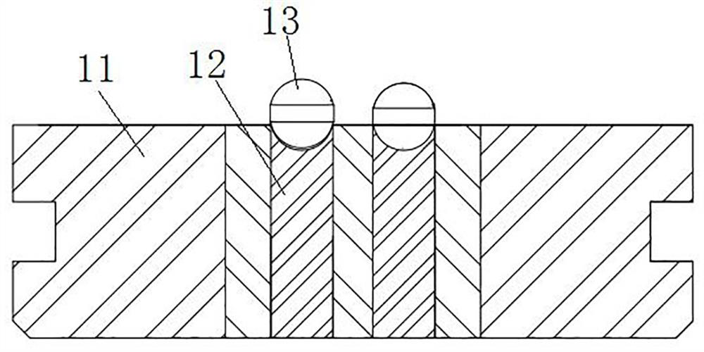
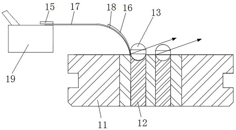
[0053] Such as figure 2As shown, the powder molding machine includes a molding die 11, a lower punch 12 and an upper punch (not shown), and the opposite ends of the upper punch and the lower punch 12 are provided with ball sockets, and the upper punch and the lower punch 12 During the relative movement in the up and down direction, the powdery material in the mold cavity of the forming die 11 is squeezed to form the billet 13, and then the upper punch moves upward, and the lower punch 12 moves upward relative to the forming die 11 to demoulding. Location.

[0054] In this embodiment, a material shoe 19 is provided on the side of the forming mold 11, and the material shoe 19 reciprocates along the horizontal direction to send the powdery material into the mold cavity of the forming mold 11, wherein the material shoe 19 is an existing mature product , which will not be repeated here.

[0055] In this embodiment, a ball blank demoulding device is provided on the material shoe ...

Embodiment 2

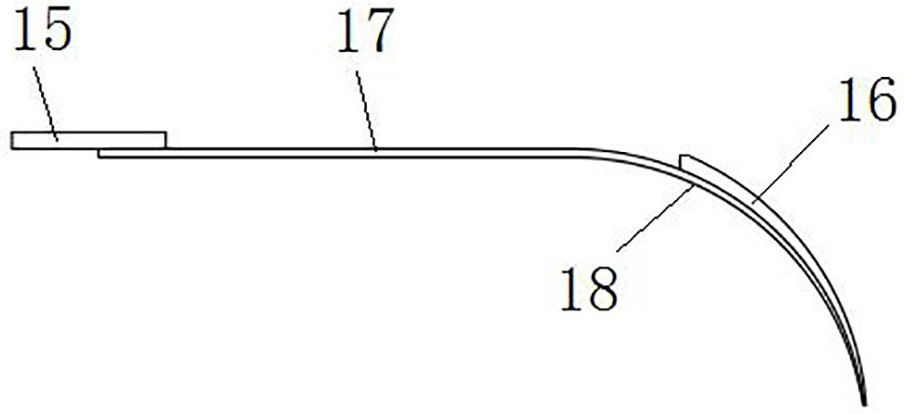
[0066] The difference between this embodiment and Embodiment 1 is that in Embodiment 1, the horizontal section 17 is bonded and fixed on the upper surface of the shoe 19 through the foam 15, so that the horizontal section 17 has a certain movable margin in the up and down direction. In this embodiment, the horizontal section is glued and fixed on the upper surface of the material shoe through a rubber pad, so that the horizontal section has a certain movable margin in the up and down direction, wherein the lower side of the rubber pad is coated with glue.

Embodiment 3

[0068] The difference between this embodiment and Embodiment 1 is that in Embodiment 1, the horizontal section 17 is fixed on the upper surface of the material shoe 19 by bonding the foam 15 . In this embodiment, a slot is provided on the side of the material shoe facing the billet, and the horizontal section is inserted into the slot to achieve fixation, wherein the width of the slot in the up and down direction is slightly larger than the thickness of the horizontal section, so that the horizontal section The segment has a certain margin of activity in the up and down direction, so that the plectrum has a certain margin in the up and down direction.


PUM


Abstract

The invention relates to a ball-billet demolding device and a powder forming machine. The ball-billet demolding device comprises a pick and a buffer layer, wherein the pick comprises a horizontal section and an arc-shaped section, the horizontal section is connected to a shoe, so that the pick moves horizontally along with the shoe, and the arc-shaped section is bended downward and a concave surface of the arc-shaped section faces downward; the buffer layer is arranged on a convex surface of the arc-shaped section, and when the pick moves toward a ball-billet, the buffer layer is used for being matched with the ball-billet in a jacking manner to push the ball-billet out of a ball socket. As the arc-shaped section of the pick jacks the ball-billet, the ball-billet is subjected to an obliqueupward jacking force, so that the ball-billet can be pushed out from the ball socket with a small jacking force. As the buffer layer is arranged on the arc-shaped section of the pick, the buffer layer is matched with the ball-billet in a jacking manner to play a buffer role, so that the jacking force of the ball-billet is reduced, the ball-billet is prevented from being damaged, and the rejectionrate of the ball-billet during demolding is reduced. Furthermore, the ball-billet demolding device is relatively simple in structure, relatively low in cost and suitable for being popularized and applied.

Description

technical field [0001] The invention relates to a ball blank demoulding device and a powder molding machine. Background technique [0002] Silicon nitride is an excellent bearing rolling element material. At present, compression molding is an important process for forming silicon nitride balls. During compression molding, the powder particles in the cavity are compacted to form a spherical blank, such as figure 1 As shown, when the upper punch is removed and the lower punch 12 moves to the demoulding position relative to the forming die 11, since the ball blank 13 is in the ball socket of the lower punch 12, and the ball blank 13 is easily Broken, so that the ball blank 13 is not easy to release from the lower punch 12. [0003] At present, in order to solve the above-mentioned problems, a sponge is generally arranged on the side of the material shoe, and the soft characteristic of the sponge is used to push the ball blank horizontally through the sponge when the material ...

Claims


Application Information

Patent Timeline
Patent Type & Authority Applications(China)
IPC IPC(8): B28B13/06B28B7/00
CPCB28B7/0097B28B13/065
Inventor 徐振宇于琦姚玉婷万磊温优优李佳琪孔永刚李海洋
Owner LUOYANG BEARING RES INST CO LTD
Why Eureka
Try Eureka