Virus killing and inactivating device for virus storage tank
A storage tank and inactivation technology, used in water supply devices, sanitary equipment for toilets, disinfection and other directions, can solve the problems of inability to automatically replace disinfectant, incomplete disinfection of virus storage tanks, and virus infection of staff, to avoid Effects of exposure to infection
- Summary
- Abstract
- Description
- Claims
- Application Information
AI Technical Summary
Problems solved by technology
Method used
Image
Examples
Embodiment 1
[0030] Such as figure 1 As shown, a virus-killing and inactivating device for a virus storage tank includes a bottom plate 1, a workbench 2, a motor 3, an automatic drainage mechanism 4 and a driving mechanism 5, and the top of the bottom plate 1 is provided with a workbench 2, and the top of the workbench 2 There is a T-shaped slot in the center, and a slot parallel to one side of the T-shaped slot is opened on the rear side of the top of the workbench 2. The motor 3 is installed on the left side of the top of the workbench 2, and the T-shaped slot on the workbench 2 is embedded There is an automatic drainage mechanism 4, and the workbench 2 is provided with a driving mechanism 5 near the automatic drainage mechanism 4, and the driving mechanism 5 cooperates with the automatic drainage mechanism 4.
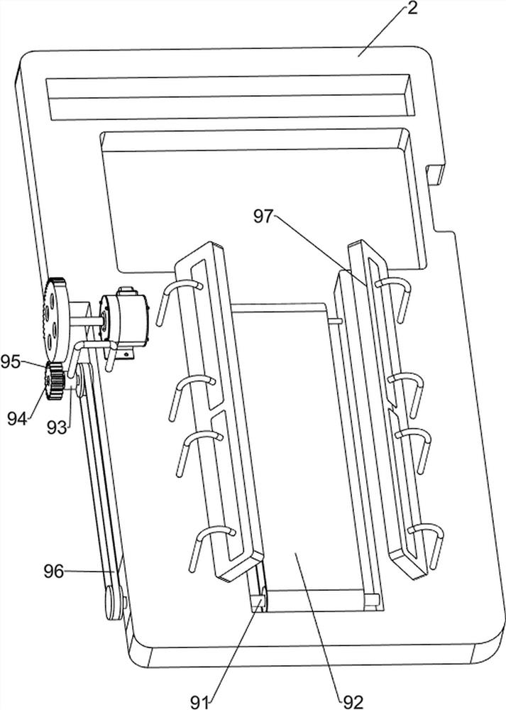
[0031]Before the virus storage tank needs to be sterilized, the staff places the virus storage tank in the driving mechanism 5, and then the staff controls the driving mechanism ...
Embodiment 2
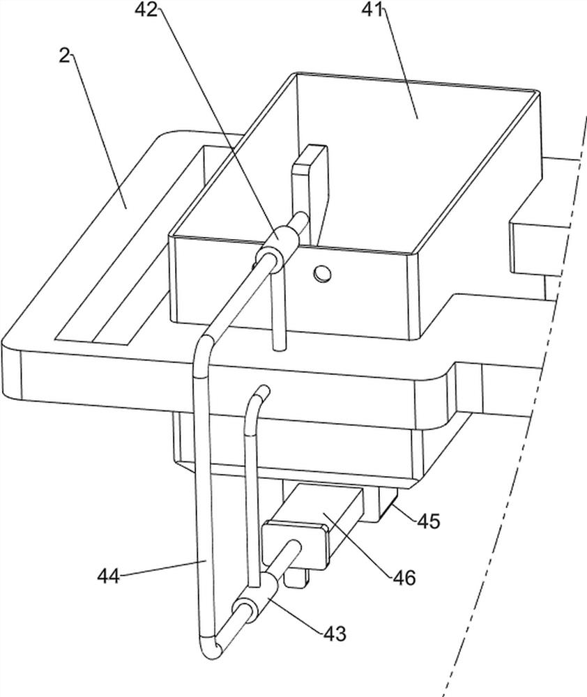
[0033] Such as figure 2 , image 3 and Figure 4 Shown, on the basis of embodiment 1, a kind of antivirus deactivation device for virus storage tank, automatic drainage mechanism 4 also includes disinfection pool 41, first guide block 42, second guide block 43, wedge-shaped Block 44, the third guide block 45, the first baffle plate 46 and the tension spring 47, a disinfection pool 41 is embedded in the T-shaped groove on the workbench 2, and a liquid outlet pipe is embedded in the center of the bottom of the disinfection pool 41 A first guide block 42 is provided on the left side of the top of the workbench 2, and a second guide block 43 is provided on the side wall of the workbench 2 close to the first guide block 42, and the sliding type between the first guide block 42 and the second guide block 43 is A wedge-shaped block 44 with a column is connected, and a third guide block 45 is arranged on the left side of the bottom of the disinfection pool 41, and a first baffle 46...
Embodiment 3
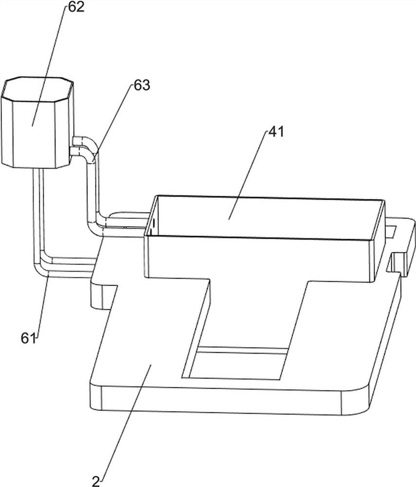
[0037] Such as Figure 5 and Figure 6 Shown, on the basis of embodiment 2, a kind of antivirus and deactivation device for virus storage tank, the side wall position of workbench 2 close to automatic drainage mechanism 4 is provided with entering disinfectant water mechanism 6, and entering disinfectant water mechanism 6 includes There is a second connecting column 61, a water tank 62 and a water outlet pipe 63. A second connecting column 61 is arranged on the left side wall of the workbench 2. A water tank 62 is arranged on the top of the second connecting column 61. Between the water tank 62 and the side wall of the disinfection pool 41 A water outlet pipe 63 is connected.
[0038] Between the workbench 2 and the water tank 62, a cleaning mechanism 7 is provided in the tank. The cleaning mechanism 7 in the tank includes a first column cover 71, a cleaning assembly 72, a chute plate 73, a moving column 74, a second column cover 75, a first Rotating shaft 76, roller 77, rev...
PUM
 Abstract
Description
Claims
Application Information
 - R&D
- Intellectual Property
- Life Sciences
- Materials
- Tech Scout
- Unparalleled Data Quality
- Higher Quality Content
- 60% Fewer Hallucinations
Browse by: Latest US Patents, China's latest patents, Technical Efficacy Thesaurus, Application Domain, Technology Topic, Popular Technical Reports.
© 2025 PatSnap. All rights reserved.Legal|Privacy policy|Modern Slavery Act Transparency Statement|Sitemap|About US| Contact US: help@patsnap.com


