A five-degree-of-freedom magnetic levitation switched reluctance motor

A switched reluctance motor and magnetic levitation technology, applied in magnetic circuits, electromechanical devices, electrical components, etc., can solve the problems of increasing the axial length of the system, reducing the critical speed of the system, and low utilization of axial space, and achieving a compact structure. , The effect of large suspension force density and large winding space

Active Publication Date: 2021-10-08
江苏大也环境有限公司
View PDF8 Cites 0 Cited by
  • Summary
  • Abstract
  • Description
  • Claims
  • Application Information

AI Technical Summary

Problems solved by technology

[0006] These three structures all need to use axial magnetic bearings alone, which increases the axial length of the system, reduces the critical speed of the system, and limits the further improvement of the speed and power. Two sets of windings are wound, namely the suspension winding and the torque winding, and the number of pole pairs of the two sets of windings must satisfy the relationship of addition and subtraction. By coordinating and controlling the current of the torque winding and the suspension winding, torque and suspension force are generated at the same time. Torque Strong coupling between control and suspension control
[0007] Invention patent number: 201610399393.7, patent name: an integrated five-degree-of-freedom magnetic levitation direct drive motor; invention patent number: 201610399391.8, patent name: an integrated five-degree-of-freedom magnetic levitation motor The motors all use two axially magnetized permanent magnets to provide bias flux, but the axial part adopts an "E"-shaped structure, and the left and right axial suspension windings form a closed path between the "E"-shaped structures. And it needs to pass through the control disc, the axial space utilization rate is low, and the axial suspension force is small

Method used


Image

  • A five-degree-of-freedom magnetic levitation switched reluctance motor
  • A five-degree-of-freedom magnetic levitation switched reluctance motor
  • A five-degree-of-freedom magnetic levitation switched reluctance motor

Examples


Embodiment Construction

[0028] In order to make the object, technical solution and advantages of the present invention clearer, the present invention will be further described in detail below in conjunction with the accompanying drawings and embodiments. It should be understood that the specific embodiments described here are only used to explain the present invention, not to limit the present invention.

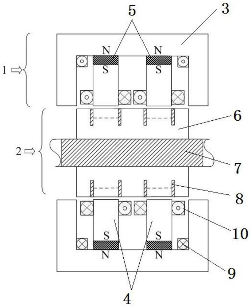
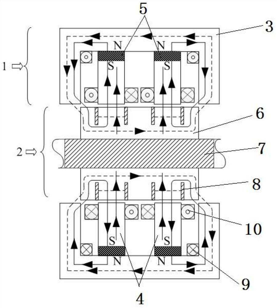
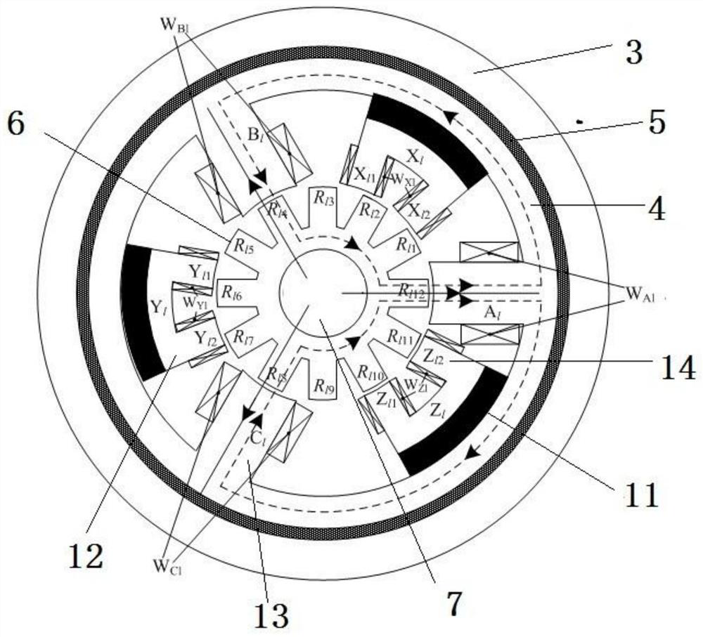
[0029] Such as figure 1 , 2 As shown, a five-degree-of-freedom magnetic levitation switched reluctance motor includes a stator 1 and a rotor 2, and the rotor 2 is coaxially sleeved inside the stator 1. The rotor 2 includes a rotating shaft 7 and a rotor iron core 6, the rotor iron core 6 is cylindrical and the rotor iron core 6 is sleeved on the outside of the rotating shaft 7; two groups of identical rotor teeth are arranged at a distance on the outer wall of the rotor iron core 6, Each group of rotor teeth has 12 teeth evenly distributed along the circumference, such as image 3 , the teeth in...


PUM


Abstract

The invention discloses a five-degree-of-freedom magnetic levitation switched reluctance motor, which includes a stator and a rotor. The stator is composed of an axial stator core, a permanent magnet ring, a motor stator core, a magnetic isolation aluminum block, Torque iron core, the torque iron core is connected to the motor stator core through a magnetic isolation aluminum block, the motor stator core is connected to the axial stator core through a permanent magnet ring, and three suspension teeth are evenly distributed inside each motor stator core , the radial suspension winding is wound on the suspension teeth, and there are two torque teeth on the inner side of each torque iron core, and the torque windings are wound on the torque teeth, and the axial suspension winding is located between the motor stator core and the axial stator iron core. Between the cores, and close to the inner side of the stator core in the axial direction; the rotor includes the rotating shaft and the rotor core, the rotor core is cylindrical, and the surface of the rotor core is directly opposite to the motor stator core and as wide as the motor stator core. The rotor teeth are evenly distributed, and the two sides of the equal-width rotor core are respectively provided with magnetic isolation aluminum rings that do not penetrate the rotor core.

Description

technical field [0001] The invention belongs to the field of motor manufacturing, in particular to a five-degree-of-freedom magnetic levitation switched reluctance motor with short axial length and high critical speed. Background technique [0002] The magnetic levitation switched reluctance motor is a new type of high-speed special motor. To realize the stable levitation of the magnetic levitation switched reluctance motor rotor, active control force must be applied simultaneously on the four radial degrees of freedom and the axial single degree of freedom. The traditional five-degree-of-freedom magnetic levitation switched reluctance motor usually has the following three structures: [0003] 1. It is composed of 1 bearing magnetic bearing and 2 two-degree-of-freedom magnetic levitation switched reluctance motors; [0004] 2. It is composed of an axial magnetic bearing, a radial magnetic bearing and a two-degree-of-freedom magnetic levitation switched reluctance motor; ...

Claims


Application Information

Patent Timeline
Patent Type & Authority Patents(China)
IPC IPC(8): H02N15/00H02K3/28H02K1/14H02K1/24
CPCH02K1/146H02K1/24H02K3/28H02K2213/03H02N15/00
Inventor 杨泽斌叶小婷丁琪峰孙晓东卢承领吴家杰梅海涛
Owner 江苏大也环境有限公司
Why Eureka
Try Eureka