


Quick Research
Generate reliable direction feasibility study reports for your R&D in just a few steps.

Technical Q&A
Discover and master advanced knowledge NOW. Basics, ideas, possibilities, all at once.

Find Solutions
As an expert in R&D theories, this can generate solutions to your technical problems instantly.

Evaluate Feasibility
Analyze your overall solution with one click, know your potential R&D risks in advance.

Monitor Landscape
Get weekly tech updates, stay abreast of the latest tech innovations and key insights.
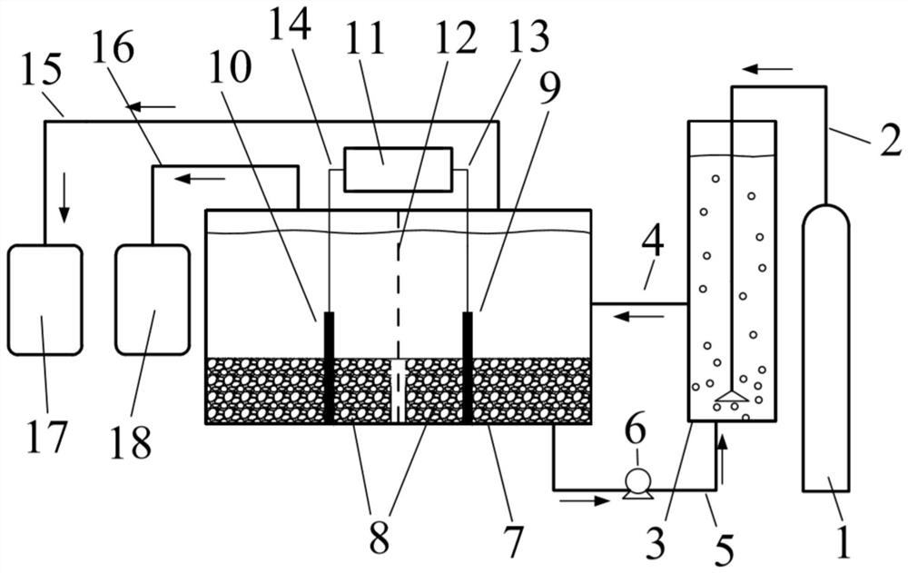
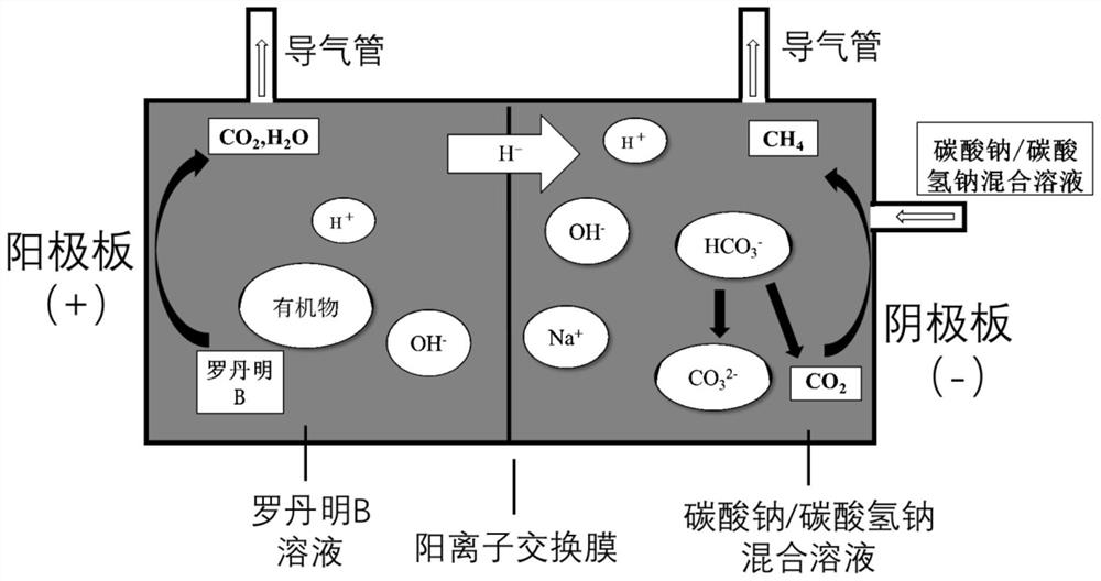
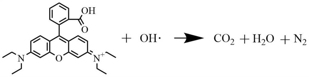
Device and method for producing methane by coupling printing and dyeing wastewater treatment with three-dimensional electrode
A technology of printing and dyeing wastewater and three-dimensional electrodes, which is applied in electrolytic organic production, water/sewage treatment, chemical instruments and methods, etc., can solve the problems of low quantum efficiency and low utilization rate of photogenerated electrons, etc., to avoid waste and save costs , fully dissolved effect
- Summary
- Abstract
- Description
- Claims
- Application Information
AI Technical Summary
Problems solved by technology
Method used
Image

Examples
Embodiment 1
[0034] Electrolyte generation tank and electrolyzer cathode compartment are pre-filled with Na 2 CO 3 Solution, the concentration is 10g / L, the solution volume in the electrolyte generation tank is 100mL, and the solution volume in the cathode chamber of the electrolytic cell is 250mL; the initial concentration of rhodamine B wastewater added in the anode chamber of the electrolyzer is changed to 100 and 150mg / L, and the volume is 250mL , pH=7. CO before electrolysis 2 The storage tank feeds CO into the electrolyte generation tank at a constant flow rate of 0.05L / min 2 Gas for 20 minutes until the pH of the liquid in the electrolyte generating tank reaches 6.8. With a current density of 50mA / cm 2 After electrolysis for 30 minutes, the removal rate and amount of TOC in the anode chamber, the amount of methane produced and the Faradaic efficiency of the anode and cathode chambers were calculated.
[0035]
Embodiment 2
[0037] Electrolyte generation tank and electrolyzer cathode compartment are pre-filled with Na 2 CO 3 Solution, the concentration is 10g / L, the solution volume in the electrolyte generation tank is 100mL, and the solution volume in the cathode chamber of the electrolytic cell is 250mL; the initial concentration of rhodamine B wastewater added in the anode chamber of the electrolyzer is changed to 100 and 150mg / L, and the volume is 250mL , pH=7. CO before electrolysis 2 The storage tank feeds CO into the electrolyte generation tank at a constant flow rate of 0.05L / min 2 Gas for 20 minutes until the pH of the liquid in the electrolyte generating tank reaches 6.8. With a current density of 50mA / cm 2 Electrolyze for 60 minutes, during the process of electrolysis, CO is still fed into the electrolyte generating tank at a constant flow rate of 0.05L / min 2 Gas, calculate the removal rate and amount of TOC in the anode chamber, the amount of methane produced and the Faradaic effi...
PUM
 Abstract
Description
Claims
Application Information
 - R&D Engineer
- R&D Manager
- IP Professional
- Industry Leading Data Capabilities
- Powerful AI technology
- Patent DNA Extraction
Browse by: Latest US Patents, China's latest patents, Technical Efficacy Thesaurus, Application Domain, Technology Topic, Popular Technical Reports.
© 2024 PatSnap. All rights reserved.Legal|Privacy policy|Modern Slavery Act Transparency Statement|Sitemap|About US| Contact US: help@patsnap.com