
A laser beam combining system based on a square fiber beam combiner

An optical fiber combiner and laser beam combining technology, applied in lasers, laser devices, laser parts and other directions, can solve problems such as poor stability, inconvenient thermal management, and difficult to solve heat dissipation problems, so as to improve stability and facilitate heat dissipation. Management, simple structure effect

Active Publication Date: 2021-03-19
LASER FUSION RES CENT CHINA ACAD OF ENG PHYSICS
View PDF14 Cites 2 Cited by
  • Summary
  • Abstract
  • Description
  • Claims
  • Application Information

AI Technical Summary

Problems solved by technology

The synthesis technology based on polarizing prism is to realize the coherent synthesis of multiple beams by means of cascading combination of polarization beam combiner; the synthesis technology based on diffraction element mainly uses the principle of reversible optical path to reversely use the diffraction optical element to realize multi-beam Synthesis, the above two methods are to convert the fiber laser beam into a space beam. When the number of synthetic laser beams increases, the number of space optical components used will increase, which will greatly increase the complexity of the beam combination system, poor stability, and difficult to solve heat dissipation problems. , not easy for thermal management
The fiber combiner based on the fused tapered fiber bundle is to put multiple optical fibers into the glass tube for tapering. The input optical fiber becomes thinner gradually, and the laser beam is coherently combined through the core gathering. Although it is an all-fiber structure, it reduces the The complexity of the system, but because this synthesis method is formed through multiple optical fibers, side lobes will inevitably appear, which will affect the combined beam quality and synthesis efficiency; synthesis technology based on the principle of optical waveguide self-imaging It mainly uses the self-imaging effect, that is, multiple input laser beams will be periodically imaged in the optical waveguide. It has the potential to completely eliminate side lobes, and can achieve a synthesis efficiency close to 100% and a beam quality close to 1 in coherent synthesis. Therefore, Combining technology based on the principle of optical waveguide self-imaging is the first choice for laser coherent beam combining
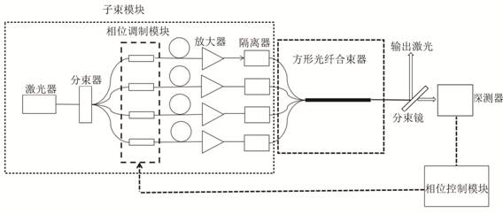
[0004] The existing laser beam combining system mainly includes three modules: sub-beam module, beam combining module and phase control module. Laser beam combining systems based on different principles have different beam combining module structures. Most of the beam combining modules of the laser beam combining system based on the imaging principle adopt a complex optical system space structure, that is, after the multiple laser beams of the sub-beam module are arranged or collimated, the beams are combined using spatial optical elements, such as through a spatial microlens After being collimated, it is driven into the optical waveguide device. Due to the need for spatial optical components, this beam combining module is highly complex and has poor stability. In addition, there is a combined power caused by the heating of the end face of the output fiber of the sub-beam module and the difficulty in heat dissipation of the optical waveguide device. Difficult to improve

Method used


Image

  • A laser beam combining system based on a square fiber beam combiner
  • A laser beam combining system based on a square fiber beam combiner

Examples


Embodiment 1

[0032] In this example, if figure 1 The coherent combining of 4 optical fibers is shown as an example. The 4 optical fibers are arranged into a 2*2 array in the beam combiner, the square optical fiber is divided into 4 square sub-areas, and the 4 optical fibers are combined with the corresponding areas in the square optical fiber. Make a vertical connection and ensure that the center of the fiber coincides with the center of the corresponding square sub-area. After the output beams of the 4 optical fibers are combined through the square fiber combiner of the present invention, the combined beam quality M 2 =1.16, the beam combining efficiency of the laser beam combining system is 99.3%, and according to figure 2 It can be seen that the beam synthesized in this embodiment has no beam side lobes.

Embodiment 2

[0034] In this embodiment, taking the coherent combination of 9 optical fibers as an example, arrange the 9 optical fibers into a 3*3 array, divide the square optical fiber into 9 square sub-areas, and divide the 9 optical fibers into the corresponding square sub-areas in the square optical fiber. The area is connected vertically, and the center of the optical fiber coincides with the center of the corresponding square sub-area. After the output lasers of the 9 optical fibers are combined through the square optical fiber combining module of the present invention, the combined beam quality M 2 If it is less than 1.3, the beam combining efficiency of the laser beam combining system is greater than 99%.

[0035] In summary, it can be seen that the laser beam combining system disclosed in the present invention can realize the laser beam combining technology based on the principle of optical waveguide self-imaging with a simple structure. The beam quality after beam combining is c...


PUM


Abstract

The invention discloses a laser beam combining system based on a square fiber beam combiner. The laser beam combining system includes: a sub-beam module, a beam combiner, a phase control module and a laser detector, wherein the beam combiner further includes: multiple The pigtails, glass tubes and square optical fibers of the first optical fiber, the multiple pigtails are arranged in a square array, and are connected vertically with the square optical fibers, and the glass tube covers the outer circumference of the multiple pigtails to protect and strengthen the connection. The laser beam combining system disclosed in the present invention can realize the laser beam combining technology based on the principle of optical waveguide self-imaging with a simple structure, which improves the stability of the performance of the beam combining system and reduces the complexity of the laser beam combining system. The beam quality of the laser beam combining system is close to 1, and the beam combining efficiency is close to 100%.

Description

technical field [0001] The invention belongs to the field of fiber lasers, in particular to a laser beam combining system based on a square fiber beam combiner. Background technique [0002] Fiber lasers have the advantages of high conversion efficiency, good beam quality, convenient thermal management, and compact structure. They are widely used in industrial, optical communication, and national defense fields. However, limited by factors such as thermal damage and nonlinear effects, the power of a single single-mode fiber laser cannot be increased infinitely. power output laser. The current fiber laser coherent combining technology can be divided into sub-aperture coherent combining technology and common aperture coherent combining technology according to the different beam combining methods of each laser subunit. Sub-aperture coherent combination means that each sub-beam is output by a separate aperture, there is a certain distance between the centers of each beam in th...

Claims


Application Information

Patent Timeline
Patent Type & Authority Patents(China)
IPC IPC(8): H01S3/23H01S3/067
CPCH01S3/06729H01S3/2383
Inventor 闫玥芳陶汝茂张昊宇刘玙楚秋慧王建军林宏奂颜冬林黄珊黄智蒙
Owner LASER FUSION RES CENT CHINA ACAD OF ENG PHYSICS
Learn More