New energy automobile battery cooling device
A new energy vehicle and cooling device technology, applied in the direction of secondary batteries, battery pack components, circuits, etc., can solve the problems of easy reduction of battery life, battery damage, fan cooling can not meet the rapid cooling requirements, etc., to achieve extended use The effect of longevity
- Summary
- Abstract
- Description
- Claims
- Application Information
AI Technical Summary
Problems solved by technology
Method used
Image
Examples
Embodiment 1
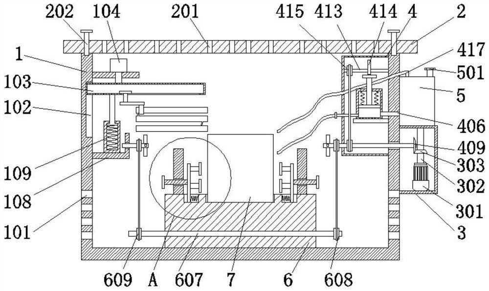
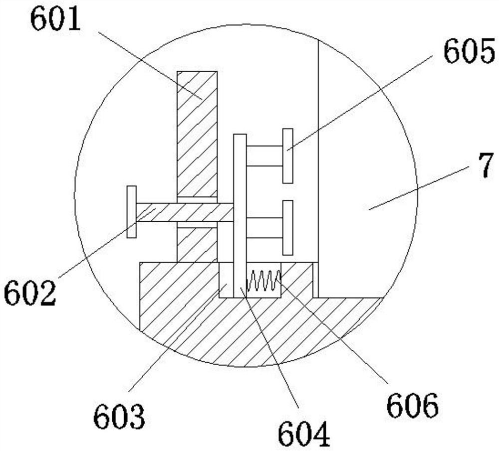
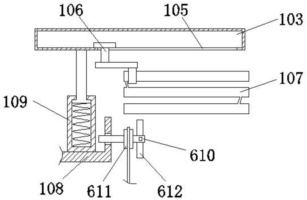
[0031] refer to Figure 1-5, a new energy vehicle battery cooling device, including a box 1 and a battery body 7, the inner wall of the box 1 is provided with a first chute 102, the first chute 102 is slidably connected to a sliding box 103, the bottom of the sliding box 103 A slider 106 is slidably connected, and the bottom of the slider 106 is fixedly connected with a heat dissipation pipe 107. The heat dissipation pipe 107 is an annular pipe, and the heat dissipation pipe 107 is provided with a water inlet and a water outlet. 3. There is a motor 301 inside the connection shell 3, the output end of the motor 301 is connected to the first rotating shaft 302 in rotation, the inner wall of the box body 1 is fixedly connected to the protective shell 4, and the protective shell 4 is rotationally connected to the first rotating shaft 302. The second rotating shaft 408 of the connecting shell 3 is fixedly connected with the coolant tank 5, the inner wall of the box body 1 is fixedl...
Embodiment 2
[0036] refer to Figure 1-4 , a new energy vehicle battery cooling device, including a box 1 and a battery body 7, the inner wall of the box 1 is provided with a first chute 102, the first chute 102 is slidably connected to a sliding box 103, the bottom of the sliding box 103 A slider 106 is slidably connected, and the bottom of the slider 106 is fixedly connected with a heat dissipation pipe 107. The heat dissipation pipe 107 is an annular pipe, and the heat dissipation pipe 107 is provided with a water inlet and a water outlet. 3. There is a motor 301 inside the connection shell 3, the output end of the motor 301 is connected to the first rotating shaft 302 in rotation, the inner wall of the box body 1 is fixedly connected to the protective shell 4, and the protective shell 4 is rotationally connected to the first rotating shaft 302. The second rotating shaft 408 of the connecting shell 3 is fixedly connected with the coolant tank 5, the inner wall of the box body 1 is fixed...
Embodiment 3
[0041] refer to Figure 1-4 , a new energy vehicle battery cooling device, including a box 1 and a battery body 7, the inner wall of the box 1 is provided with a first chute 102, the first chute 102 is slidably connected to a sliding box 103, the bottom of the sliding box 103 A slider 106 is slidably connected, and the bottom of the slider 106 is fixedly connected with a heat dissipation pipe 107. The heat dissipation pipe 107 is an annular pipe, and the heat dissipation pipe 107 is provided with a water inlet and a water outlet. 3. There is a motor 301 inside the connection shell 3, the output end of the motor 301 is connected to the first rotating shaft 302 in rotation, the inner wall of the box body 1 is fixedly connected to the protective shell 4, and the protective shell 4 is rotationally connected to the first rotating shaft 302. The second rotating shaft 408 of the connecting shell 3 is fixedly connected with the coolant tank 5, the inner wall of the box body 1 is fixed...
PUM
 Abstract
Description
Claims
Application Information
 - R&D
- Intellectual Property
- Life Sciences
- Materials
- Tech Scout
- Unparalleled Data Quality
- Higher Quality Content
- 60% Fewer Hallucinations
Browse by: Latest US Patents, China's latest patents, Technical Efficacy Thesaurus, Application Domain, Technology Topic, Popular Technical Reports.
© 2025 PatSnap. All rights reserved.Legal|Privacy policy|Modern Slavery Act Transparency Statement|Sitemap|About US| Contact US: help@patsnap.com


