


Quick Research
Generate reliable direction feasibility study reports for your R&D in just a few steps.

Technical Q&A
Discover and master advanced knowledge NOW. Basics, ideas, possibilities, all at once.

Find Solutions
As an expert in R&D theories, this can generate solutions to your technical problems instantly.

Evaluate Feasibility
Analyze your overall solution with one click, know your potential R&D risks in advance.

Monitor Landscape
Get weekly tech updates, stay abreast of the latest tech innovations and key insights.
Control circuit
A technology for controlling circuits and controlling signals, which is applied in the field of circuits and can solve problems such as the inability to achieve real-time control of clock sources
- Summary
- Abstract
- Description
- Claims
- Application Information
AI Technical Summary
Problems solved by technology
Method used
Image

Examples
Embodiment 1
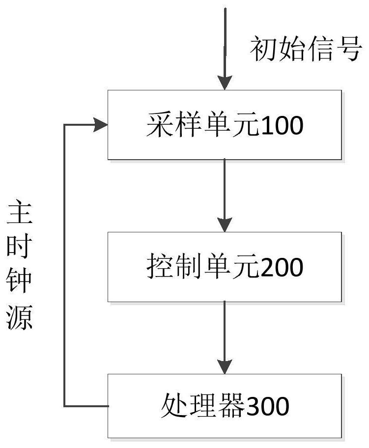
[0041]This embodiment includes all the content in the above embodiments, and will not be repeated here, wherein, the sampling unit 100 in this embodiment includes: the plurality of delay units and a plurality of triggers;
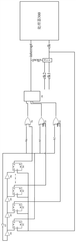
[0042] There are one or more delay units as initial signal input terminals in the plurality of delay units, and each of the delay units as initial signal input terminals is respectively used to receive the setting signal and connect N delay units in series, where N is a natural number;
[0043] There are a plurality of delay units serving as output terminals of the sample signal among the plurality of delay units, and different delay units output sample signals with different delay times;
[0044] The sample input end of each flip-flop is connected to a delay unit as the output end of the sample signal, wherein different flip-flops are connected to different delay units, and the clock input end of each flip-flop is connected to The main clock source is use...
Embodiment 2
[0054] This embodiment includes all the content in Embodiment 1, and will not be repeated here. In this embodiment, among multiple flip-flops, the output end of a flip-flop is connected in series with an inverter as the initial signal input end. The delay unit is connected.
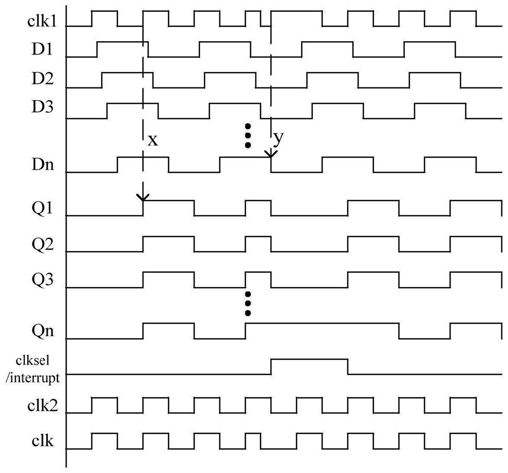
[0055] In this embodiment, the phase of the output signal of the flip-flop is reversed by 180 degrees after passing through the inverter, so that the signal at the output end of the flip-flop can be converted into a transition signal and input to the delay unit, so that the sample signal can become a transition signal , in order to sample the sample signal.
[0056] Preferably, among the plurality of flip-flops, the flip-flop which takes the sample signal with the shortest delay time as the input signal is connected in series with the inverter.
[0057] In this embodiment, by connecting the sample signal with the shortest delay time as the input signal flip-flop and the inverter in series, the delay unit...
Embodiment 3
[0059] This embodiment includes all the content of Embodiment 1 and Embodiment 2, which will not be repeated here, wherein, in this embodiment, the control unit 200 includes a plurality of XOR gates and OR gate groups,
[0060] The first input ends of the plurality of XOR gates are all connected to the output end of the same flip-flop in the plurality of flip-flops, and the second input ends of the plurality of XOR gates are respectively connected to the output ends of other flip-flops, wherein , the second input ends of different XOR gates are connected to different flip-flops;
[0061] The input terminals of the OR gate group are connected to the output terminals of the plurality of exclusive OR gates, and are used to generate control signals according to the output signals of the plurality of exclusive OR gates, and transmit the control signals to the processor 300, so that the processor 300 controls the abnormal situation of the master clock source according to the control...
PUM
 Abstract
Description
Claims
Application Information
 - R&D Engineer
- R&D Manager
- IP Professional
- Industry Leading Data Capabilities
- Powerful AI technology
- Patent DNA Extraction
Browse by: Latest US Patents, China's latest patents, Technical Efficacy Thesaurus, Application Domain, Technology Topic, Popular Technical Reports.
© 2024 PatSnap. All rights reserved.Legal|Privacy policy|Modern Slavery Act Transparency Statement|Sitemap|About US| Contact US: help@patsnap.com