Driving shaft identification system

An identification system and drive shaft technology, applied in the field of vehicle identification, can solve problems such as affecting disassembly and replacement, difficulty in disassembly, etc., and achieve the effect of reducing the probability of corrosion

Pending Publication Date: 2021-01-29
广东科达计量科技有限公司
View PDF0 Cites 0 Cited by
  • Summary
  • Abstract
  • Description
  • Claims
  • Application Information

AI Technical Summary

Problems solved by technology

[0003] In view of the deficiencies in the prior art, the purpose of the present invention is to provide a drive shaft identification system to solve the problem that the bolts of the support structure on the fixed camera head are installed in the above-mentioned background technology, and the screw parts are hidden and exposed. , it is easy to be difficult to disassemble after being damp and rusted, which affects the problem of later disassembly and replacement. The present invention realizes the exposure of part of the screw part of the bolt that fixes the support structure on the camera, and achieves the purpose of hiding the bolt.

Method used


Image

  • Driving shaft identification system
  • Driving shaft identification system

Examples


Embodiment Construction

[0017] In order to make the technical means, creative features, goals and effects achieved by the present invention easy to understand, the present invention will be further described below in conjunction with specific embodiments.

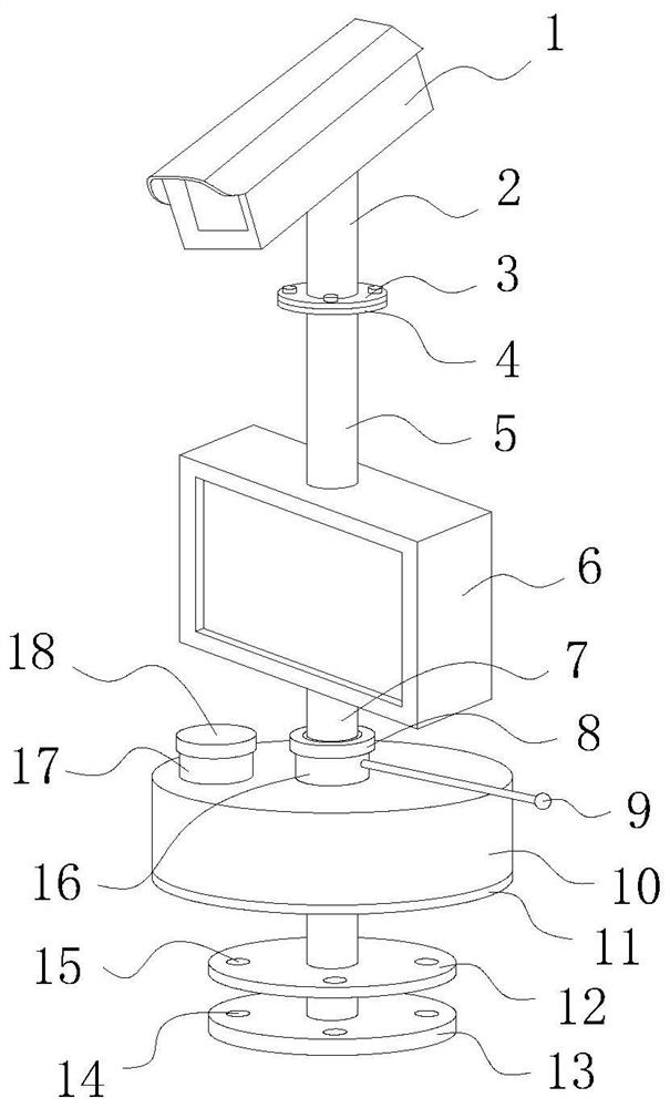
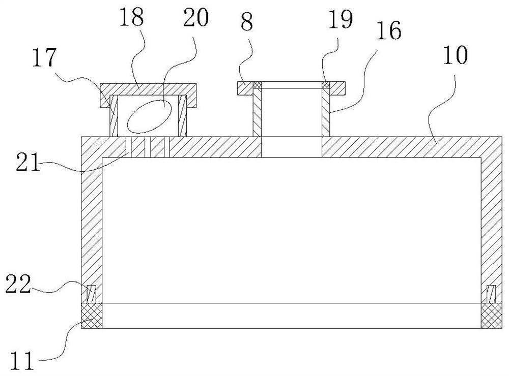
[0018] see figure 1 and figure 2 , the present invention provides a technical solution: a driving shaft identification system, comprising a camera 1, a hollow tube 5 installed on the lower surface of the camera 1, and a display 6 installed at the lower end of the hollow tube 5, the lower surface of the display 6 is fixedly connected with a support rod 7. The lower end of the support rod 7 is fixedly connected with a base 13, and the upper surface of the base 13 is provided with a plurality of mounting holes 14 for inserting bolts in a circular equidistant manner, and the bolts fixing the base 13 are fixed on the ground through the mounting holes 14, and the completion The fixing of the position of the base 13, that is, the position of the suppor...


PUM


Abstract

The invention provides a driving shaft identification system. The driving shaft identification system comprises a camera, a hollow pipe installed on the lower surface of the camera and a display installed at the lower end of the hollow pipe, wherein the lower surface of the display is fixedly connected with a support rod; the lower end of the support rod is fixedly connected with a base; a plurality of mounting holes for inserting bolts are annularly formed in the upper surface of the base at equal intervals; a support disk which is kept at a certain distance from the base is arranged at the upper side of the base, and the support disk is arranged on the support rod in a sleeving manner and is fixedly connected with the support rod; a plurality of circular holes aligned with the mounting holes are annularly formed in one surface, facing the base, of the support disk at equal intervals; and a circular cover capable of covering the support disk and the base is arranged at the upper sideof the support disk, and the circular cover is arranged on the support rod in a sleeving manner. Compared with the prior art, the driving shaft identification system has the following beneficial effects that a part of screw parts of the bolts for fixing the support structure on the camera are exposed, and the purpose of storing the bolts in a hidden manner is achieved.

Description

technical field [0001] The invention relates to a drive shaft identification system, which belongs to the technical field of vehicle identification. Background technique [0002] The Ministry of Transport of my country recently promulgated the "Regulations on the Administration of Overrun Transport Vehicles Driving on Highways", which pointed out that the number of drive shafts has become an important measure of weight overruns. At present, the camera is often used to collect and identify the drive shaft information of the vehicle. The support structure on the camera is often fixed on the ground with bolts, but after the bolts that fix the support structure on the camera are installed, the screw part is hidden. And in an exposed state, it is easy to be difficult to disassemble after being damp and rusted, which will affect the later disassembly and replacement. Contents of the invention [0003] In view of the deficiencies in the prior art, the purpose of the present inve...

Claims


Application Information

Patent Timeline
Patent Type & Authority Applications(China)
IPC IPC(8): F16M11/20
CPCF16M11/20
Inventor 晏立顺伍习成赖景光
Owner 广东科达计量科技有限公司
Why Eureka
Try Eureka