Backbone beam bridge rear-mounted cantilever rib plate mixed connection structure with bearing function

A backbone beam bridge and hybrid technology, applied in bridges, bridge parts, bridge materials, etc., can solve problems such as restricting construction efficiency and construction quality, long construction period of wet joint scheme, increased risk of high-altitude operations, etc., to reduce high-altitude operations The effect of reducing operational risks, improving construction quality, and reducing on-site construction period

Pending Publication Date: 2021-01-29
SHANGHAI MUNICIPAL ENG DESIGN INST GRP
View PDF0 Cites 2 Cited by
  • Summary
  • Abstract
  • Description
  • Claims
  • Application Information

AI Technical Summary

Problems solved by technology

However, the construction period of the wet joint scheme is longer, and temporary vertical supports must be erected during the long period from the hoisting of the post-installation boom to the concrete strength reaching the standard
Considering that there are a large number of rib wet joints discretely along the longitudinal bridge direction, if the construction site has a process of erecting supports one by one - pouring wet joints - removing the supports after the maintenance is completed, the construction efficiency and construction quality will be severely restricted , Significantly increase the risk of working at heights

Method used


Image

  • Backbone beam bridge rear-mounted cantilever rib plate mixed connection structure with bearing function
  • Backbone beam bridge rear-mounted cantilever rib plate mixed connection structure with bearing function
  • Backbone beam bridge rear-mounted cantilever rib plate mixed connection structure with bearing function

Examples


Embodiment Construction

[0034] In order to facilitate the understanding of the present invention, the present invention will be described in more detail below in conjunction with the accompanying drawings and preferred embodiments, but the protection scope of the present invention is not limited to the following specific embodiments.

[0035] Unless otherwise defined, all technical terms used hereinafter have the same meanings as commonly understood by those skilled in the art. The terminology used herein is only for the purpose of describing specific embodiments, and is not intended to limit the protection scope of the present invention.

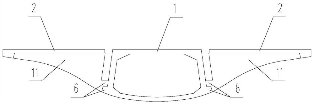
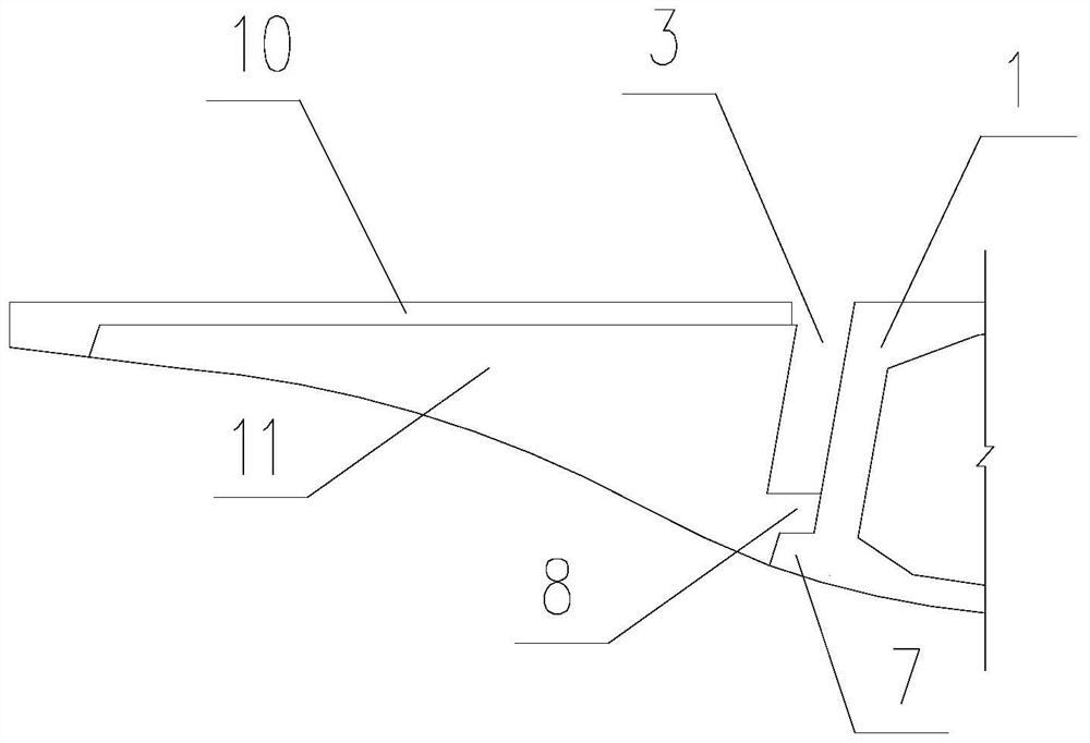
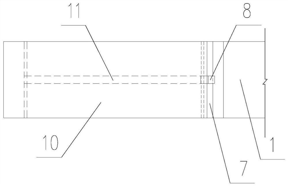
[0036] This embodiment adopts a back-mounted cantilever-rib hybrid connection structure of a spine girder bridge with supports, as shown in the accompanying drawings. It differs from the prior art in that it is suitable for segmental prefabricated composite cross-section spine girder bridges, and the cantilever 2 is a segmentally assembled prefabricated concrete c...


PUM


Abstract

The invention provides a backbone beam bridge rear-mounted cantilever rib plate mixed type connecting structure with a bearing function. The backbone beam bridge rear-mounted cantilever rib plate mixed type connecting structure is suitable for a composite-section backbone beam bridge with prefabricated sections. A rear-mounted cantilever arm is a prefabricated concrete member assembled by sections, and follows the construction time sequence that the core longitudinal beam is erected step by step after being constructed; prefabricated supports are arranged on the lower edges of the roots of thecantilever rib plates and connected with the supports of the core longitudinal beams in a matched and dry mode; the cantilever rib plate is provided with a vertical post-mounted cantilever rib platewet joint above the prefabricated support, and the vertical post-mounted cantilever rib plate wet joint is in wet joint with the core longitudinal beam; the prefabricated support and the rear-mountedcantilever rib plate wet joint are combined to form novel mixed connection. The reasonable rib plate transverse mixing type connecting structure can ensure reliable connection and convenient construction, reduces the risk of aloft work, and is suitable for various bridges with complex sections and ultrahigh gradual change and curve sections.

Description

technical field [0001] The invention belongs to the technical field of bridge components and construction thereof, in particular to a back-mounted cantilever-rib hybrid connection structure of a backbone girder bridge with supports. Background technique [0002] Segmentally prefabricated and assembled concrete bridges are in line with the national industrial development direction, and have many advantages such as green environmental protection, small impact on the environment and traffic, convenient transportation, fast construction, beautiful appearance, durability and low life-cycle cost. In recent years, they have been used in domestic railways, highways, It has been widely promoted and applied in rail transit and municipal engineering, and has achieved good results. [0003] At present, for large prefabricated segmented box girders with wide bridge decks, limited by the transportation size and hoisting weight, the conventional method is to use a split multi-box section. ...

Claims


Application Information

Patent Timeline
Patent Type & Authority Applications(China)
IPC IPC(8): E01D19/00E01D19/06E01D21/06E01D2/04E01D101/28
CPCE01D2/04E01D19/00E01D19/06E01D19/067E01D21/06E01D2101/285
Inventor 郭济卢永成齐新王猛严搏张智然
Owner SHANGHAI MUNICIPAL ENG DESIGN INST GRP
Why Eureka
Try Eureka