
Flywheel assembly machining equipment with chipping cleaning function

A processing equipment and functional technology, applied in the direction of metal processing equipment, metal processing, metal processing machinery parts, etc., can solve the problems of difficult removal of debris, impact on service life, and reduction of surface finish of finished products, so as to achieve strong applicability and prolong Mechanism life, the effect of improving the cleaning effect

Inactive Publication Date: 2021-01-29
DONGGUAN UNIV OF TECH
View PDF0 Cites 4 Cited by
  • Summary
  • Abstract
  • Description
  • Claims
  • Application Information

AI Technical Summary

Problems solved by technology

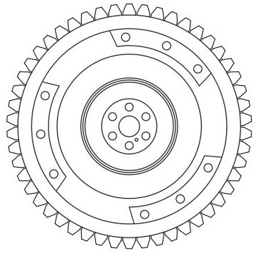
[0003] The existing flywheel assembly processing equipment, common problems are: the processing technology of the flywheel assembly in the existing manufacturing process is: blank forging - blank detection - quenching and tempering treatment - lathe processing - hobbing - drilling ——Quenching treatment—Flaw detection—High temperature tempering—Inspection—Packaging; After the drilling is completed, there are many drilling debris on the surface of the flywheel assembly, and the debris is adsorbed on the surface of the flywheel assembly and pasted In the gear on the outer periphery of the flywheel assembly, the debris is not easy to remove from the gear, reducing the surface finish of the finished product in the subsequent process and affecting the service life

Method used


Image

  • Flywheel assembly machining equipment with chipping cleaning function
  • Flywheel assembly machining equipment with chipping cleaning function
  • Flywheel assembly machining equipment with chipping cleaning function

Examples


Embodiment Construction

[0029] The following will clearly and completely describe the technical solutions in the embodiments of the present invention with reference to the accompanying drawings in the embodiments of the present invention. Obviously, the described embodiments are only some, not all, embodiments of the present invention.

[0030] In the description of the present invention, unless otherwise stated, the meaning of "plurality" is two or more; the terms "upper", "lower", "left", "right", "inner", "outer" , "front end", "rear end", "head", "tail", etc. indicate the orientation or positional relationship based on the orientation or positional relationship shown in the drawings, and are only for the convenience of describing the present invention and simplifying the description, rather than Indicates or implies that the device or element referred to must have a particular orientation, be constructed and operate in a particular orientation, and therefore should not be construed as limiting the...


PUM


Abstract

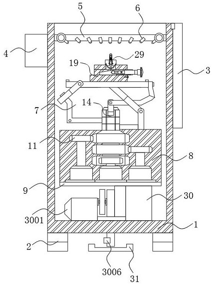
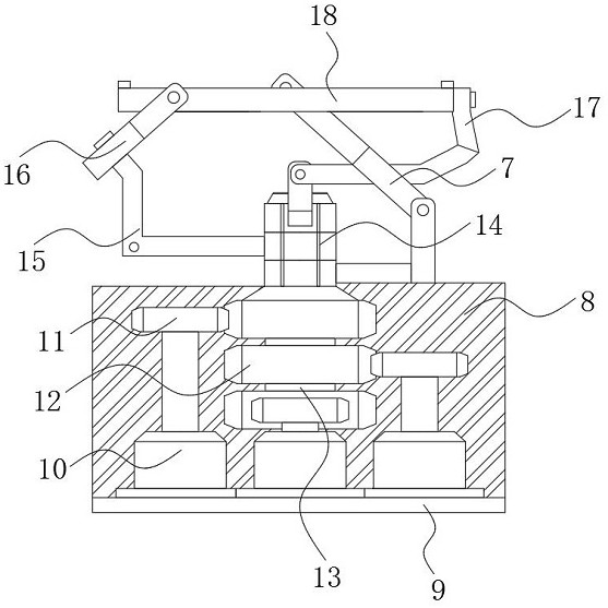
The invention discloses flywheel assembly machining equipment with a chipping cleaning function, and relates to the technical field of automobile part machining. The flywheel assembly machining equipment specifically comprises a box body, a coaxial parallel mechanical platform, a wedge auxiliary rapid clamping mechanism, a self-locking supporting mechanism and an automatic overturning and discharging mechanism, wherein a damping base is arranged at the bottom end of the box body, and the automatic overturning and discharging mechanism is arranged on one side of the bottom end of the box body.According to the flywheel assembly machining equipment with the chipping cleaning function, the coaxial parallel mechanical platform is arranged, the mechanism is a spherical parallel mechanical platform with a coaxial input shaft, and the mechanism is controlled by three stepping motors through gear transmission and nine rotating joints, any angle position can be achieved in a three-dimensional space, the machining angle of a workpiece arranged in a loading platform at the top end of the coaxial parallel mechanical platform can be changed at will under the assistance of the coaxial parallel mechanical platform, and by matching with air nozzles arranged at the surface end of an annular air injection pipe in an array mode, the comprehensive chipping cleaning process of a flywheel assembly material clamped by the wedge auxiliary rapid clamping mechanism is realized.

Description

technical field [0001] The invention relates to the technical field of automobile parts processing, in particular to a flywheel assembly processing equipment with a debris cleaning function. Background technique [0002] The flywheel assembly is mostly used for high-speed and high-power diesel engines, and is an important part of the diesel engine starting system; the flywheel assembly is installed on the flywheel, and the diesel engine is started by meshing with the gear of the starter motor; the conventional flywheel assembly adopts an integral structure, The flywheel assembly is connected to the flywheel through bolts. The flywheel assembly bears a large impact load during operation, and the work is very unstable. Usually, after a specific working cycle is completed, it needs to be removed for maintenance or replacement. Therefore, pay attention to the surface accuracy of the flywheel assembly in the processing process. And smoothness has become an effective way to improv...

Claims


Application Information

Patent Timeline
IPC IPC(8): B23Q11/00B23Q3/00B23Q7/00
CPCB23Q3/00B23Q7/00B23Q11/0042
Inventor 邓君
Owner DONGGUAN UNIV OF TECH
Learn More