
Medical self-service terminal equipment

A self-service terminal and equipment technology, which is applied to coin-operated equipment with instrument control, coin-operated equipment and instruments for distributing discrete items, etc., can solve problems such as increasing the burden on patients or their families, wasting manpower, and cross-infection. , to achieve the effect of improving safety and convenience, avoiding accidental movement, and improving convenience

Inactive Publication Date: 2021-01-22
深圳市环阳通信息技术有限公司
View PDF0 Cites 3 Cited by
  • Summary
  • Abstract
  • Description
  • Claims
  • Application Information

AI Technical Summary

Problems solved by technology

[0002] With the continuous development of information technology in the medical and health industry, various electronic equipment applications emerge in an endless stream. Now all the work of the hospital requires the direct intervention of medical staff. In some non-essential links, manpower investment has been increased. Although it can provide patients with convenient services and quick response , but the phenomenon of manpower waste is extremely serious, and 7*24 hours of no-vacancy service cannot be realized, and the accuracy of manual business processing cannot be fully guaranteed. Therefore, medical self-service terminals are widely used so that patients can use them by themselves;
[0003] The prior art has the following deficiencies: due to the large number of patients in the hospital and the dense population, when an infectious virus is prevalent, it is easy to cause cross-infection through the actual operation of the medical self-service terminal, which is dangerous to a certain extent. Disinfection not only wastes the use time of medical self-service terminals, but also causes a waste of manpower

Method used


Image

  • Medical self-service terminal equipment
  • Medical self-service terminal equipment
  • Medical self-service terminal equipment

Examples


Embodiment Construction

[0026] In order to enable those skilled in the art to better understand the technical solutions of the present invention, the present invention will be further described in detail below in conjunction with the accompanying drawings.

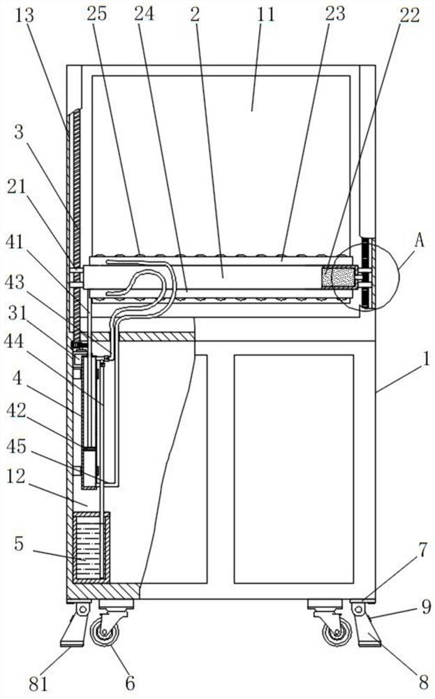
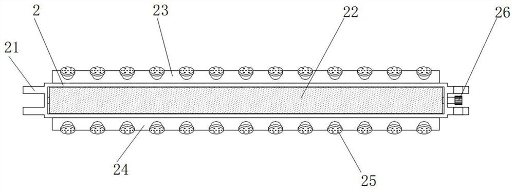
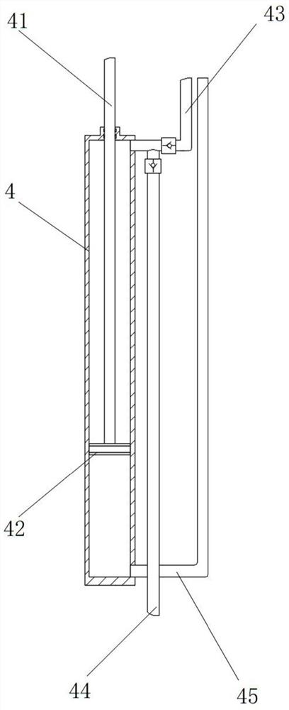
[0027] The present invention provides such Figure 1-5 The shown medical self-service terminal equipment includes a medical self-service terminal main body 1, an operation panel 11 is arranged on the top of the medical self-service terminal main body 1, and an installation cabinet 12 is arranged on the bottom of the medical self-service terminal main body 1 , both sides of the operation panel 11 are fixedly connected with lifting guide grooves 13, the outside of the operation panel 11 is provided with a cleaning box 2, and the two ends of the cleaning box 2 are respectively fixedly connected with two side convex plates 21 , the side convex plates 21 at both ends of the cleaning box 2 are respectively slidably connected to the inside of the two li...


PUM


Abstract

The invention discloses medical self-service terminal equipment which comprises a medical self-service terminal main body. An operation panel is arranged at the top of the medical self-service terminal main body, a mounting cabinet is arranged at the bottom of the medical self-service terminal main body, and lifting guide grooves are fixedly connected to the two sides of the operation panel. And acleaning box is arranged on the outer side of the operation panel, the two ends of the cleaning box are fixedly connected with two side protruding plates correspondingly, and the side protruding plates at the two ends of the cleaning box are slidably connected into the two lifting guide grooves correspondingly. According to the invention, after the equipment is used every time, a stepping motor is controlled to drive the cleaning box to ascend and descend for one time, disinfectant is sprayed out for disinfection, and after the cleaning box reaches the top, the stepping motor can be controlled to drive the cleaning box to descend for wiping so that the use safety and convenience of the medical self-service terminal main body are greatly improved.

Description

technical field [0001] The invention relates to the field of medical equipment technology, in particular to a medical self-service terminal equipment. Background technique [0002] With the continuous development of information technology in the medical and health industry, various electronic equipment applications emerge in an endless stream. Now all the work of the hospital requires the direct intervention of medical staff. In some non-essential links, manpower investment has been increased. Although it can provide patients with convenient services and quick response , but the phenomenon of manpower waste is extremely serious, and 7*24 hours of no-vacancy service cannot be realized, and the accuracy of manual business processing cannot be fully guaranteed. Therefore, medical self-service terminals are widely used so that patients can use them by themselves; [0003] The prior art has the following deficiencies: due to the large number of patients in the hospital and the d...

Claims


Application Information

Patent Timeline
Patent Type & Authority Applications(China)
IPC IPC(8): G07F17/00
CPCG07F17/00
Inventor 李新平肖宗文
Owner 深圳市环阳通信息技术有限公司
Learn More