Direct-current system storage battery health condition and internal fault monitoring device

A monitoring device and health status technology, which is applied in the field of DC system battery health status and internal fault monitoring devices, can solve problems such as power supply system paralysis, insufficient control of the health status of battery packs, and failure to monitor battery ground faults.

Pending Publication Date: 2021-01-22
JIANGSU ELECTRIC POWER CO +3
View PDF0 Cites 1 Cited by
  • Summary
  • Abstract
  • Description
  • Claims
  • Application Information

AI Technical Summary

Problems solved by technology

[0002] When the DC power system is in normal operation, the battery is in a floating charge standby state. In the case of AC power failure or other accidents, the battery is the only energy supplier for the load. Once a problem occurs, the power supply system will be paralyzed, resulting in equipment outage and other major operational accident
At present, there are still two problems to be solved in the operation and maintenance of the battery pack: 1. Simple voltage inspection cannot support the prediction of battery performance, resulting in insufficient grasp of the health status of the battery pack, and it is difficult to predict the remaining capacity and health status of the battery. It is difficult to detect when there is an open circuit inside the battery; 2. In the actual operation of the DC power supply system, faults such as DC grounding often occur, but the grounding fault of the battery cannot be monitored at present
[0003] The current operating DC systems basically have real-time online monitoring data functions such as battery pack voltage, bus voltage, charge and discharge current, floating charge current, cell voltage, cell internal resistance, capacity, and abnormal switch position alarms. The latest DC system is online The monitoring device has even added the internal resistance monitoring function, but at present, it is basically just monitoring the data and giving a simple alarm, and does not make full use of the monitoring data to provide battery packs with safety control and detection throughout the life cycle, and there is a problem that cannot be realized. parts and weak points

Method used


Image

  • Direct-current system storage battery health condition and internal fault monitoring device

Examples


Embodiment Construction

[0021] The specific implementation of a DC system storage battery health status and internal fault monitoring device according to the present invention will be described in detail below in conjunction with the accompanying drawings.

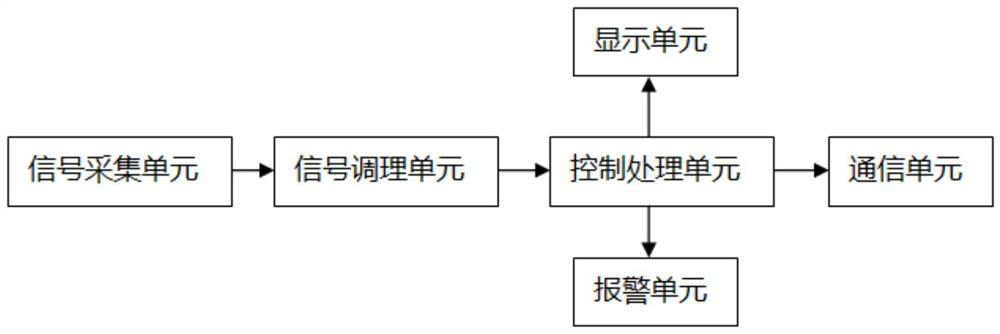
[0022] Such as figure 1 As shown, the monitoring device of the present invention includes a signal acquisition unit, a signal conditioning unit, a control processing unit, a display unit, an alarm unit and a communication unit, and the signal acquisition unit is connected with the signal conditioning unit and the control processing unit, The control processing unit is also connected to the display unit, the alarm unit, and the communication unit respectively; the monitoring device collects the working information of the battery, performs safety monitoring in the whole life cycle, and judges whether the battery is working Whether the condition is economical and healthy, whether there is a ground fault, and when there is an abnormality, an alarm wi...


PUM


Abstract

The invention provides a direct-current system storage battery health condition and internal fault monitoring device. The monitoring device comprises a signal acquisition unit, a signal conditioning unit, a control processing unit, a display unit, an alarm unit and a communication unit. The monitoring device collects the working information of the storage battery, carries out safety monitoring inthe whole life cycle, judges whether the working condition of the storage battery is economical and healthy or not, judges whether a grounding fault occurs or not, and gives an alarm in time when an abnormality occurs, so that the economical, healthy, safe and reliable work of the storage battery is ensured. The invention provides the direct-current system storage battery health condition and internal fault monitoring device, which can reliably monitor the safety of a storage battery in real time and ensure the working reliability of the storage battery.

Description

technical field [0001] The invention belongs to the technical field of electric power detection, and in particular relates to a device for monitoring the health status and internal faults of a storage battery in a DC system. Background technique [0002] When the DC power system is in normal operation, the battery is in a floating charge standby state. In the case of AC power failure or other accidents, the battery is the only energy supplier for the load. Once a problem occurs, the power supply system will be paralyzed, resulting in equipment outage and other major operational accidents. At present, there are still two problems to be solved in the operation and maintenance of the battery pack: 1. Simple voltage inspection cannot support the prediction of battery performance, resulting in insufficient grasp of the health status of the battery pack, and it is difficult to predict the remaining capacity and health status of the battery. It is difficult to detect when there is...

Claims


Application Information

Patent Timeline
Patent Type & Authority Applications(China)
IPC IPC(8): G01R31/382G01R31/389G01R31/392
CPCG01R31/382G01R31/389G01R31/392
Inventor 宋延辉陆文锋杨政瞿永军
Owner JIANGSU ELECTRIC POWER CO
Why Eureka
Try Eureka