
Large-format optical polarization pattern generation device and generation method

A polarization pattern and generation device technology, applied in optics, optical elements, nonlinear optics, etc., can solve the problems of photosensitive adhesive layer contact, low precision, easy to generate static electricity, etc., to overcome single polarization orientation, improve resolution, eliminate patchwork effect

Active Publication Date: 2021-01-19
SUZHOU UNIV
View PDF13 Cites 3 Cited by
  • Summary
  • Abstract
  • Description
  • Claims
  • Application Information

AI Technical Summary

Problems solved by technology

However, there are the following problems: static electricity is easily generated during the friction process, which will cause the breakdown of the thin film transistor, and due to the fluff dust generated during the friction process, cleaning and drying processes must be added after friction, which reduces production efficiency
[0005] Among them, the problems of mask engraving polarization pattern technology are: overlaying is too difficult, low efficiency; low precision; it is difficult to produce large format; the mask is in contact with the photosensitive adhesive layer on the wafer, causing damage
[0006] The periodic liquid crystal alignment technology obtained by the holographic interference method can only achieve a specific periodic polarization pattern, and cannot achieve arbitrary polarization pattern writing
[0007] The polarization orientation technology based on the liquid crystal spatial modulator is a programmable control device that can modulate the phase and amplitude of the incident light. A single projection orientation can realize the pattern recording of different orientations of liquid crystals in different selected areas. However, if the imaging system is enlarged system, the sample size is large, the pixel unit size is also large, and it is impossible to output high-precision polarization patterns

Method used


Image

  • Large-format optical polarization pattern generation device and generation method
  • Large-format optical polarization pattern generation device and generation method
  • Large-format optical polarization pattern generation device and generation method

Examples


Embodiment Construction

[0071] In order to make the purpose, technical solutions and advantages of the present invention clearer, the technical solutions in the embodiments of the present invention will be clearly and completely described below in conjunction with the accompanying drawings in the embodiments of the present invention. Obviously, the described embodiments are only Some, but not all, embodiments of the invention. Based on the embodiments of the present invention, all other embodiments obtained by persons of ordinary skill in the art without making creative efforts belong to the protection scope of the present invention.

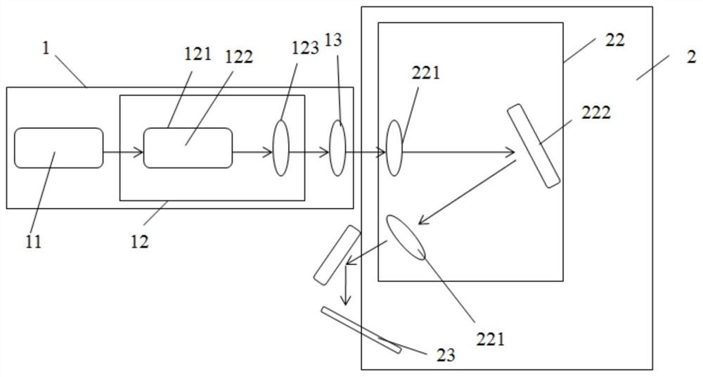
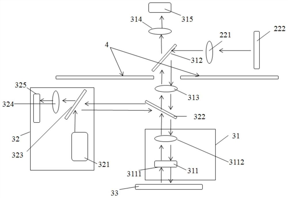
[0072] An embodiment of the present invention provides a large-format optical polarization pattern generation device, such as figure 1 and figure 2 As shown, the device includes sequentially connected parts illumination part 1, polarization pattern generation part 2, miniature imaging part 311, imaging detection and splicing part 3;

[0073] The lighting component 1...


PUM


Abstract

The invention discloses a large-format optical polarization pattern generation device which comprises an illumination component, a polarization pattern generation component, a miniature imaging component and an imaging detection and splicing component which are connected in sequence. The illumination component is used for realizing single polarization collimation of uniform surface light spots; the polarization pattern generation part comprises a quarter-wave plate and a phase modulator and is used for outputting a polarization pattern; the miniature imaging component is used for miniaturizingthe polarization pattern output by the polarization pattern generation part and writing the miniaturized polarization pattern into the photosensitive material; the imaging detection and splicing component comprises an imaging detection sub-part and a focal length calibration sub-part; and the imaging detection sub-part comprises a double-light-path pattern monitoring imaging assembly and a pattern splicing assembly. The integrated optical system, the motion control system and the detection system have the advantages that the single-exposure polarization pattern is high in precision, optionally controllable and high in efficiency, large-area optical polarization patterns can be realized, and the like.

Description

technical field [0001] The invention relates to the field of liquid crystal display, in particular to a large-format optical polarization pattern generation device and generation method. Background technique [0002] Liquid crystals are widely used in information display, optical and photonic devices and other fields; liquid crystals can further realize the amplitude, phase and polarization modulation of light according to the designed orientation arrangement, which plays an important role in these applications, so the orientation of liquid crystals Alignment control methods have become a research hotspot in academic and industrial production. The existing technologies disclosed at present are mainly rubbing alignment technology and light-controlled alignment technology: [0003] The patent application number CN201721714019.8 discloses an orientation layer rubbing device used in the production of liquid crystal display screens; rubbing orientation is to use materials such as...

Claims


Application Information

Patent Timeline
IPC IPC(8): G02B27/28G02F1/1337
CPCG02B27/286G02F1/133788
Inventor 黄文彬郑致刚钱逻毅
Owner SUZHOU UNIV
Learn More