
Framework type buffer device and setting method thereof

A buffer device, skeleton technology, used in mechanical equipment, springs/shock absorbers, vibration suppression adjustment, etc., can solve the problems of short service life, limited application occasions, small damping, etc., to reduce application costs and wide range of applications , the effect of reducing the impact force

Active Publication Date: 2021-01-15
ZHONGBEI UNIV
View PDF5 Cites 2 Cited by
  • Summary
  • Abstract
  • Description
  • Claims
  • Application Information

AI Technical Summary

Problems solved by technology

Existing damping elements such as rubber damping are simple in structure and easy to process and manufacture, but have poor high temperature resistance and fatigue resistance; hydraulic damping has good cushioning effect and controllable damping, but the design and maintenance are complicated; the application occasions of these damping elements are limited, and the performance The design and maintenance needs to be further improved, the bearing capacity is poor, the damping is small, the anti-aging and corrosion resistance are poor, the manufacturing process is complicated, and the service life is short; moreover, the arrangement of the existing buffer devices is based on experience to determine the number of buffer devices. As well as the location of the layout, there is no unified basis, and the technical requirements for the staff are relatively high. Therefore, it is necessary to improve the above problems

Method used


Image

  • Framework type buffer device and setting method thereof
  • Framework type buffer device and setting method thereof
  • Framework type buffer device and setting method thereof

Examples


Embodiment Construction

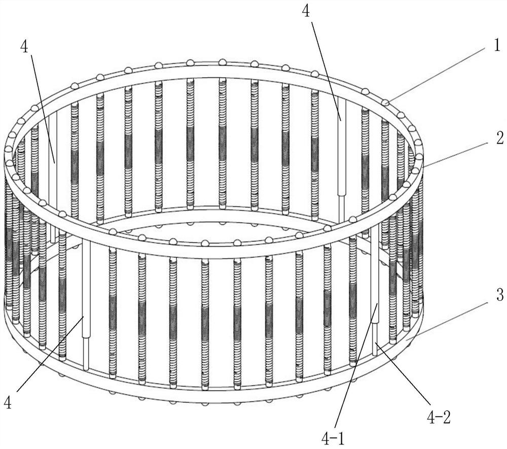
[0039] Attached below Figure 1-7 An embodiment of the present invention is described so as to clearly and completely describe the technical solution. Obviously, the described embodiment is only a part of the embodiments of the present invention, rather than all the embodiments.

[0040] In describing the present invention, it should be understood that the terms "upper", "lower", "front", "rear", "left", "right", "top", "bottom", "inner", " The orientation or positional relationship indicated by "outside", etc. is based on the orientation or positional relationship shown in the drawings, which is only for the convenience of describing the present invention and simplifying the description, rather than indicating or implying that the referred device or element must have a specific orientation, so as to Specific orientation configurations and operations, therefore, are not to be construed as limitations of the invention.

[0041] Skeleton cushioning devices, such as figure 1 As...


PUM


Abstract

The invention provides a framework type buffer device and a setting method thereof. A plurality of height adjusting devices which are connected with an upper framework and can make the upper frameworkor a lower framework freely ascend and descend up and down are fixed to the lower framework; a plurality of combined type elastic buffer pieces are arranged between every two adjacent height adjusting devices; and the upper ends and the lower ends of the combined type elastic buffer pieces are fixedly connected with the upper framework and the lower framework respectively. Due to the fact that the plurality of height adjusting devices are arranged between the upper framework and the lower framework, the upper framework or the lower framework can ascend and descend freely up and down, and a guide basis is provided for downward movement under pressure and movement after pressure relief; and due to the fact that the plurality of combined type elastic buffer pieces are arranged between everytwo adjacent height adjusting devices, the device can achieve the function of quickly absorbing and slowly dissipating impact energy, effectively reduces the impact force to protect a moving body, hasa reset function, is good in corrosion resistance and fatigue resistance, can be repeatedly used to reduce the application cost, can adapt to application environments with different buffer space scales, and is wide in application range.

Description

technical field [0001] The invention belongs to the technical field of vibration reduction and buffering, and specifically designs a skeleton type buffering device and a setting method thereof. Background technique [0002] Buffer devices are widely used in the fields of aerospace, automobile industry and high-speed machinery, etc. The core component of the buffer device is the damping element. Existing damping elements such as rubber damping are simple in structure and easy to process and manufacture, but have poor high temperature resistance and fatigue resistance; hydraulic damping has good cushioning effect and controllable damping, but the design and maintenance are complicated; the application occasions of these damping elements are limited, and the performance The design and maintenance needs to be further improved, the bearing capacity is poor, the damping is small, the anti-aging and corrosion resistance are poor, the manufacturing process is complicated, and the se...

Claims


Application Information

Patent Timeline
IPC IPC(8): F16F15/04F16F15/08
CPCF16F15/085
Inventor 杨伟原霞王玉帅候军伟邵晓宙鲍继轩曹志娟
Owner ZHONGBEI UNIV
Learn More