Pneumatic sample conveying pipeline fault positioning system and method
A fault location and pipeline technology, which is applied in the direction of using fluid devices to transmit sensing components, etc., can solve problems such as fault location of pneumatic sample delivery pipelines, achieve low implementation costs, reduce costs, and improve detection efficiency
- Summary
- Abstract
- Description
- Claims
- Application Information
AI Technical Summary
Problems solved by technology
Method used
Image

Examples
Embodiment 1
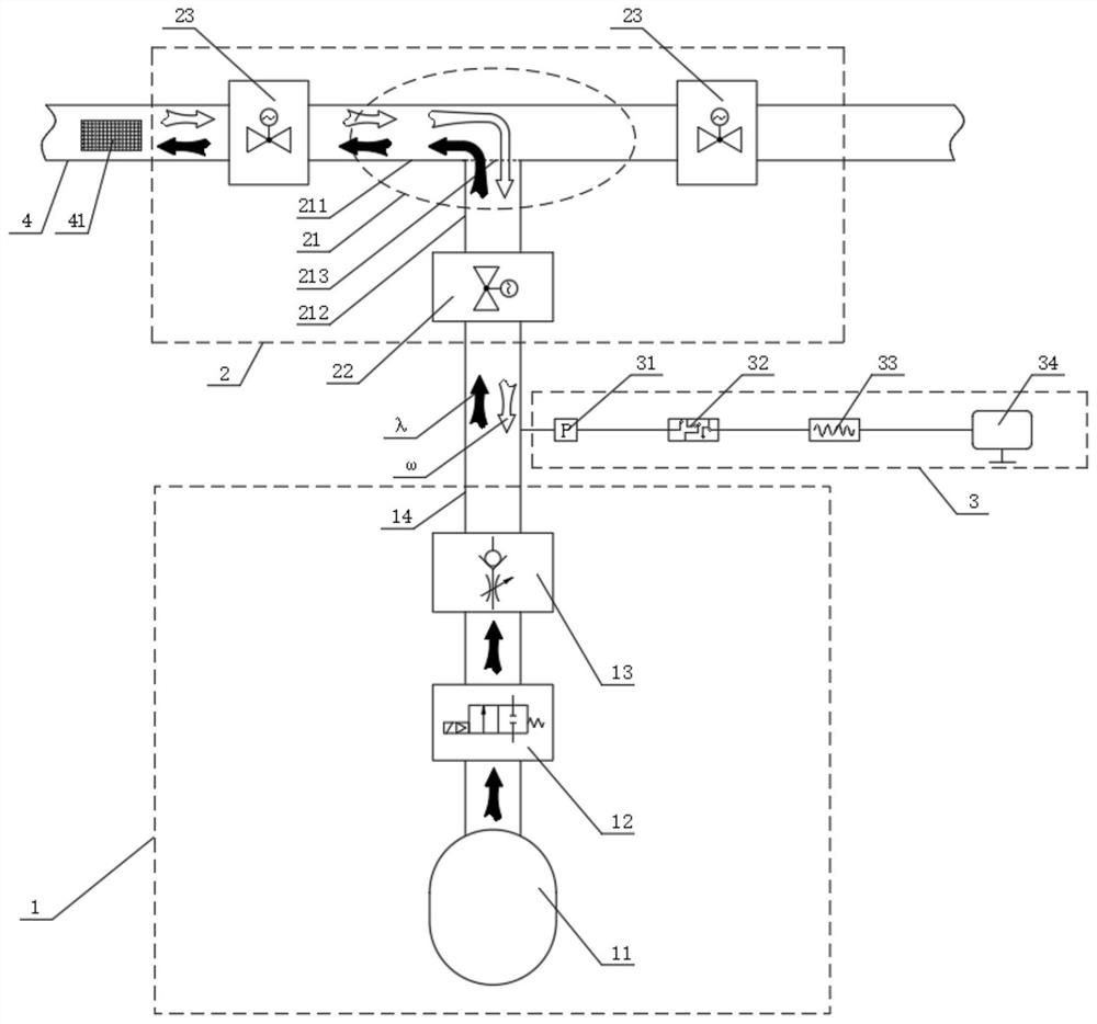
[0040] Such as figure 1 As shown, the present invention provides a fault location system for pneumatic sample delivery pipelines. The system is composed of three subsystems, including a pressure wave generation system 1, a pipeline access system 2 and a measurement and analysis system 3. The pipeline access system 2 is used for After being connected to the pneumatic sample delivery pipeline 4, the system can detect and locate the position of the obstacle 41 in the pneumatic sample delivery pipeline 4 and the type of the obstacle. The output end of the pressure wave generation system 1 is connected to the input end of the pipeline access system 2, and the measurement and analysis system 3 can be connected to the output end of the pressure wave generation system 1 or to the wall of the pipeline access system 2 , to measure the pressure wave signal inside the pipeline.
[0041] The pressure wave generation system 1 in this scheme is used to generate pressure waves with a certain...
Embodiment 2
[0044] Such as figure 1 As shown, this embodiment provides a fault location system for pneumatic sample delivery pipelines. In this embodiment, the pipeline access system 2 includes a three-way pipe 21, and the three-way pipe 21 includes a main line pipeline 211 and a branch line pipeline 212. The branch line pipeline 212 One end of the main line pipeline 211 is connected to the middle position, after the connection, the main line pipeline 221 and the branch line pipeline 212 run through, the other end of the branch line pipeline 212 is used as the input end of the pipeline access system 2, and one or both ends of the main line pipeline 211 are used as the pipeline access system 2 output terminals. The installation position of the pneumatic sample delivery pipeline fault location system, that is, the installation position of the pipeline access system 2 in the pneumatic sample delivery pipeline 4, can be any point within the range of the pneumatic sample delivery pipeline 4, w...
Embodiment 3
[0046] Such as figure 1 As shown, the basic structure of this embodiment is the same as that of Embodiment 2. On the basis of Embodiment 2, the two ends of the main line pipeline 211 are respectively provided with a main line valve 23. The main line valve 23 is preferably a ball valve, and the ball valve in the pipeline can reduce the impact on the pipeline. Effect of Shipping Samples. When the pneumatic sample delivery pipeline 4 is working, the main line valve 23 remains open. The open main line valve 23 does not affect the normal transmission of the pneumatic sample delivery pipeline 4 to the sample box. When the pneumatic sample delivery pipeline 4 breaks down, it can pass Control the switch of the main line valve 23 at both ends of the main line pipeline 211, select the pipeline on one side to detect, and when one of the main line valves 23 is closed, the pressure wave can all move in the direction of the other open main line valve 23. The working process of the system i...
PUM
 Abstract
Description
Claims
Application Information
 - R&D
- Intellectual Property
- Life Sciences
- Materials
- Tech Scout
- Unparalleled Data Quality
- Higher Quality Content
- 60% Fewer Hallucinations
Browse by: Latest US Patents, China's latest patents, Technical Efficacy Thesaurus, Application Domain, Technology Topic, Popular Technical Reports.
© 2025 PatSnap. All rights reserved.Legal|Privacy policy|Modern Slavery Act Transparency Statement|Sitemap|About US| Contact US: help@patsnap.com