A leak-proof structure for gas pipe fittings
A technology of anti-leakage and gas pipes, which is applied in the pipeline system, gas/liquid distribution and storage, instruments, etc., can solve the problems of safety hazards, gas is not easy to be discharged into the atmosphere, and gas pipelines have no active anti-leakage, so as to facilitate later maintenance, Guarantee the effect of normal operation
Active Publication Date: 2022-06-03
宁波耀通管阀科技有限公司
View PDF9 Cites 2 Cited by
- Summary
- Abstract
- Description
- Claims
- Application Information
AI Technical Summary
Problems solved by technology
[0004] The anti-leakage structure of gas pipe fittings proposed by the present invention solves the problem that the existing gas pipeline has no active anti-leakage device, and when the gas pipeline leaks, the leaked gas is not easy to be discharged into the atmosphere in time, resulting in a certain potential safety hazard
Method used
View moreImage
Smart ImageViewing Examples
Examples
Embodiment 1
Embodiment 2
Embodiment 3
Login to View More PUM
 Abstract
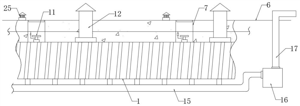
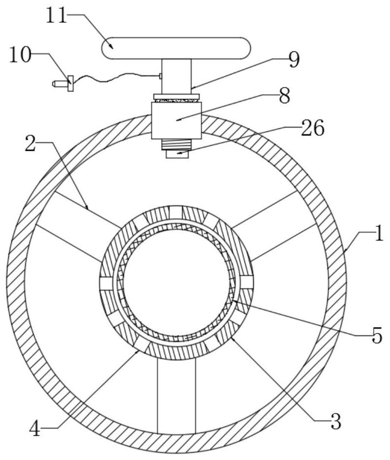
The invention discloses an anti-leakage structure of a gas pipe fitting, and relates to the technical field of gas pipeline anti-leakage. The existing gas pipeline has no active anti-leakage device, and when the gas pipeline leaks, the leaked gas is not easy to be discharged into the atmosphere in time, resulting in For problems with certain potential safety hazards, the following scheme is proposed, which includes an outer protective pipe, a transmission socket, a control computer, a water delivery pipe, the ground surface, and an inner protective pipe. The inner protective pipe is located inside the outer protective pipe, and the inner protective pipe Evenly distributed support rods are fixedly connected between the outer surface of the protective pipe and the inner wall of the outer protective pipe, and evenly distributed threaded seats are fixedly connected to the surface of the outer protective pipe, and the threaded seats are all located near the surface of the outer protective pipe side setting. The device of the present invention can not only actively dilute and discharge combustible gas, but also quickly inform nearby residents of leakage information; at the same time, it is convenient for later maintenance, and has the function of protecting gas pipes, which is suitable for popularization.
Description
An anti-leakage structure for gas pipe fittings technical field [0001] The present invention relates to the technical field of gas pipeline leakage prevention, in particular to a leakage prevention structure for gas pipe fittings. Background technique [0002] An important vehicle for transporting flammable gases such as natural gas during the gas pipeline is produced due to the leakage of the gas pipeline. There are not a few explosion accidents; gas pipelines bring hidden dangers to people's life safety to a certain extent, so gas pipeline The safety of the use of the road should be given special attention. [0003] The current gas pipelines are often purchased underground for gas transportation, and lack a certain active anti-leakage When the gas pipeline leaks, if the gas is not discharged smoothly, it is easy to cause the gas to accumulate, which will bring about There is a hidden danger of explosion, and the current gas pipeline leakage alarm device cannot be use...
Claims
Login to View More Application Information
Patent Timeline
 Patent Type & Authority Patents(China)
IPC IPC(8): F17D5/06F17D5/00G08B3/10G08B21/16
CPCF17D5/06F17D5/00G08B21/16G08B3/10
Inventor 陈磊陈明江余思国
Owner 宁波耀通管阀科技有限公司
Features
- R&D
- Intellectual Property
- Life Sciences
- Materials
- Tech Scout
- Unparalleled Data Quality
- Higher Quality Content
- 60% Fewer Hallucinations
Learn More Browse by: Latest US Patents, China's latest patents, Technical Efficacy Thesaurus, Application Domain, Technology Topic, Popular Technical Reports.
© 2025 PatSnap. All rights reserved.Legal|Privacy policy|Modern Slavery Act Transparency Statement|Sitemap|About US| Contact US: help@patsnap.com


