
Integrated structure injector for rocket engine

A rocket engine and injector technology, which is applied in the direction of rocket engine devices, machines/engines, mechanical equipment, etc., can solve the problems of complex processing technology and poor permeability, and achieve the goal of simplifying the processing process, reducing processing costs, and reducing the number of parts Effect

Inactive Publication Date: 2021-01-08
北京天兵科技有限公司
View PDF6 Cites 4 Cited by
  • Summary
  • Abstract
  • Description
  • Claims
  • Application Information

AI Technical Summary

Problems solved by technology

The overall process of forming the injector by welding is complicated, the nozzles of oxidizer and fuel are nested with each other, the liquids are directly mixed, and the mutual permeability is poor

Method used


Image

  • Integrated structure injector for rocket engine
  • Integrated structure injector for rocket engine
  • Integrated structure injector for rocket engine

Examples


Embodiment

[0045] For the thrust chamber head injector of a 30-ton liquid rocket engine, the maximum diameter is Φ393mm, the height is 188mm, the oxidant (O) is nitrous oxide, the fuel (F) is ethylene, and the propellant mixing ratio is 6.

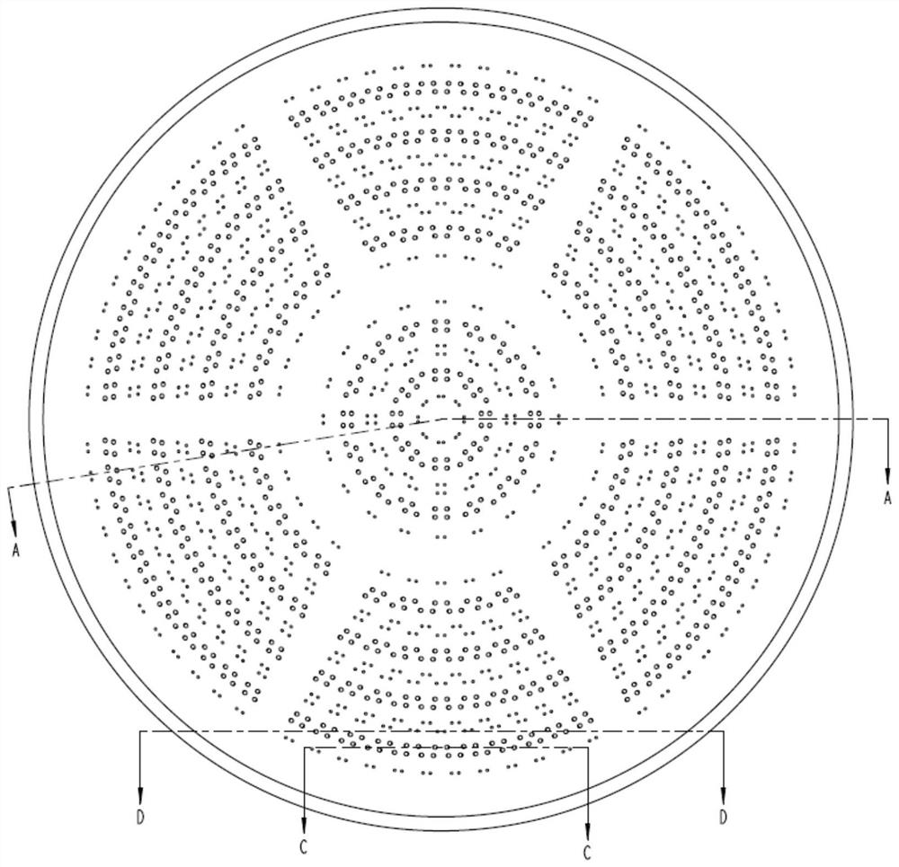
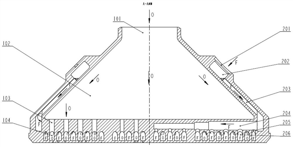
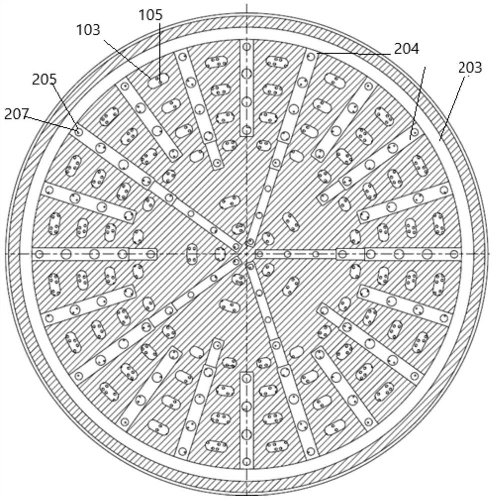
[0046] Such as figure 1 To such as Figure 5 As shown, an injector with an integrated structure provided by the present invention includes according to the fluid flow sequence:

[0047] Oxidant inlet 101, oxidant liquid collection chamber 102, oxidant distribution channel 103, oxidant ring chamber 104 and oxidant injection hole 105;

[0048] A fuel inlet 201 , a fuel liquid collection chamber 202 , a fuel delivery channel 203 , a fuel delivery channel 204 , a fuel distribution hole 205 , a fuel annular cavity 206 and a fuel injection hole 207 .

[0049] The oxidant enters the oxidant liquid collection chamber 102 from the oxidant inlet 101, passes through the oxidant distribution channels 103 arranged in the axial direction, enters six oxidant ring...


PUM


Abstract

The invention provides an integrated structure injector for a rocket engine. The integrated structure injector comprises an oxidizing agent inlet, an oxidizing agent liquid collecting cavity, oxidizing agent distribution channels, oxidizing agent annular cavities and oxidizing agent injection holes; and a fuel inlet, a fuel liquid collecting cavity, a fuel conveying channel, fuel distribution channels, fuel annular cavities and fuel injection holes are formed, and each propellant flows through the corresponding channel, then enters the corresponding annular cavity and enters the correspondinginjection hole. According to the machining method, the number of parts is effectively reduced, the machining process is simplified, the manufacturing period of the injector is shortened, the machiningcost is reduced, and meanwhile the product reliability is improved. According to the machining method, the oxidizing agent annular cavities and the fuel annular cavities are arranged in a circle andcorrespond to the injection ports correspondingly, so that the oxidizing agents and fuel are injected correspondingly; and the injection holes form injection pairs, oxidizing agent mist fans and fuelmist fans are formed through mutual impact, and mutual infiltration and mixing between the oxidizing agent mist fans and the fuel mist fans are achieved, so that it is guaranteed that the oxidizing agents and the fuel can be evenly mixed in proportion, and the combustion efficiency is improved.

Description

technical field [0001] The invention relates to the technical field of rocket engines, in particular to an injector with an integrated structure for rocket engines. Background technique [0002] The development direction of the rocket engine is to simplify the structure to improve the reliability of the engine while ensuring the performance of the engine. The injector of a traditional liquid rocket engine supplies and mixes the oxidant and fuel, and its structure becomes more complicated as its thrust increases. The injector of a general liquid rocket engine is composed of multiple parts, and then the multiple parts are connected together by various welding methods such as brazing and argon arc welding. The manufacturing cycle is long and the cost is high, which restricts the engine. The rapid verification of the scheme and the reduction of the cost of the engine product. [0003] CN106735829A discloses a welding method of a multi-part structure of a thrust chamber head in...

Claims


Application Information

Patent Timeline
Patent Type & Authority Applications(China)
IPC IPC(8): F02K9/52
CPCF02K9/52
Inventor 沈涌斌田伟枫康永来朱正辉
Owner 北京天兵科技有限公司
Learn More