DDR interface circuit fault diagnosis method and device for high-density chip

A technology of fault diagnosis device and interface circuit, which is applied in the direction of measuring device, electronic circuit testing, measuring electricity, etc., can solve problems such as invalidity, and achieve the effect of simple hardware design, saving R&D cost and cycle, and low cost.

Pending Publication Date: 2021-01-05
东莞飞思凌通信技术有限公司
View PDF0 Cites 0 Cited by
  • Summary
  • Abstract
  • Description
  • Claims
  • Application Information

AI Technical Summary

Problems solved by technology

And the operation is simple, no special technical personnel

Method used


Image

  • DDR interface circuit fault diagnosis method and device for high-density chip
  • DDR interface circuit fault diagnosis method and device for high-density chip
  • DDR interface circuit fault diagnosis method and device for high-density chip

Examples


Embodiment Construction

[0024] The present invention will be described in further detail below in conjunction with the accompanying drawings.

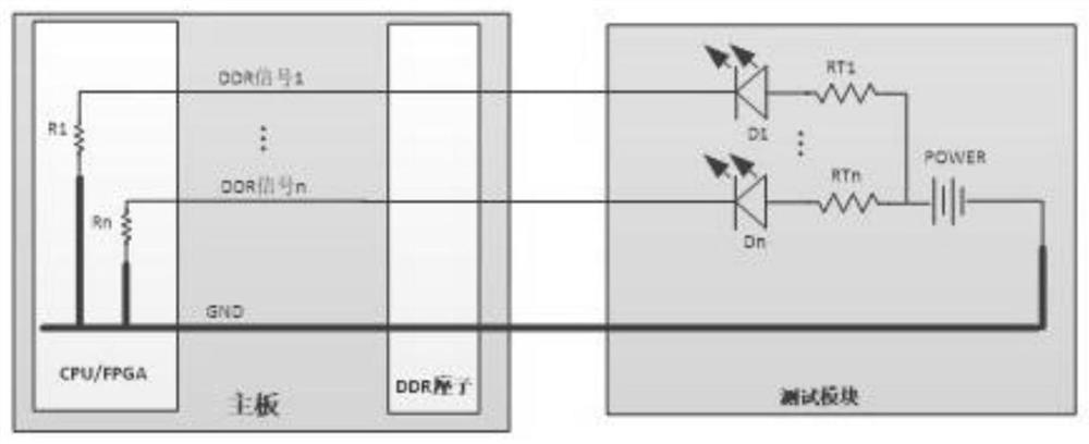
[0025] A DDR interface circuit fault diagnosis device for high-density chips, including a main board and a test module, the main board includes a chip and a DDR socket, the test module includes an LED indicator Dn, an adjustment resistor RTn and a power supply module POWER, the test The module is connected to the motherboard through the DDR socket.

[0026] Among them, the role of adjusting resistor RTn: due to the difference in the internal resistance Rn from the DDR pin to the ground of different chips, the brightness of the LED indicator light will be different. The current flowing through the LED indicator determines the brightness of the LED indicator. According to the formula, LED indicator light Dn current Idn=(Vpower-Vd1) / (Rn+RTn). Wherein Idn is the current flowing through the LED indicator Dn, Vd1 is the forward drop voltage of the LED indicator, ...


PUM


Abstract

The invention discloses a DDR interface circuit fault diagnosis method and device for a high-density chip, and the device comprises a mainboard and a test module, wherein the mainboard comprises a chip and a DDR seat; the test module comprises an LED indicating lamp Dn, an adjusting resistor RTn, and a power supply module POWER, and the test module is connected with the mainboard through the DDR seat. Compared with the prior art, the method has the advantages that hardware design is simple, software is not needed, cost is low, a mainboard does not need to be powered on, the method can adapt todifferent chips, operation is easy and visual, the research and development cost of a company can be greatly saved, and the research and development period of the company can be greatly shortened.

Description

technical field [0001] The invention relates to the technical field of high-density BGA chip circuit testing, in particular to a method and device for fault diagnosis of a DDR interface circuit of a high-density chip. Background technique [0002] At present, with the development of electronic products in the direction of miniaturization and high performance, the design density of motherboard CPU or FPGA chip is getting higher and higher. This kind of high-density BGA chip has more and more pins, and the PIN spacing is getting smaller and smaller. Among them, the DDR interface circuit of the chip occupies a lot of pin circuits. A chip is often designed to use the signals of multiple sets of DDR memory sticks. It brings challenges to the fault diagnosis of DDR circuit soldering. [0003] There are two common ways of fault diagnosis at present. [0004] One is to use professional X-ray detection equipment. Commonly used X-ray detection instruments include two-dimensional X...

Claims


Application Information

Patent Timeline
Patent Type & Authority Applications(China)
IPC IPC(8): G01R31/28G01R31/52G01R31/54
CPCG01R31/2836G01R31/52G01R31/54
Inventor 凌烽张更张越超马彬王朝章
Owner 东莞飞思凌通信技术有限公司
Why Eureka
Try Eureka