
Method and device for measuring exciton orientation of luminescent material

A technology of luminescent materials and measurement methods, applied in the direction of material excitation analysis, polarization influence characteristics, etc., can solve problems such as inaccurate results, inapplicable doped material systems, etc., achieve fast calculation speed, ensure accuracy, and simple methods Effect

Active Publication Date: 2021-01-05
武汉宇微光学软件有限公司
View PDF8 Cites 5 Cited by
  • Summary
  • Abstract
  • Description
  • Claims
  • Application Information

AI Technical Summary

Problems solved by technology

This method does not require a model, it is very simple but requires the luminescent material to be isotropic before thermal annealing and the results are not very accurate
At present, ellipsometer is commonly used to measure the optical constants of materials to determine the molecular orientation of luminescent materials. It is to measure the polarization and phase changes of linearly polarized light (S light and P light) reflected by the sample multiple times, but this measurement method is not applicable. in doped material system

Method used

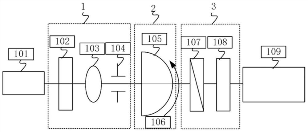

Image

  • Method and device for measuring exciton orientation of luminescent material
  • Method and device for measuring exciton orientation of luminescent material
  • Method and device for measuring exciton orientation of luminescent material

Examples


Embodiment 1

[0091] The present example concerns the exciton orientation of the pure phosphor RD. Sample A is a luminescent film made of material RD by vacuum evaporation, and its substrate is quartz glass; the theoretical thickness of material RD is 50nm, and the shape of sample A is a square with a size of about 20mm×20mm. Specifically include the following steps:

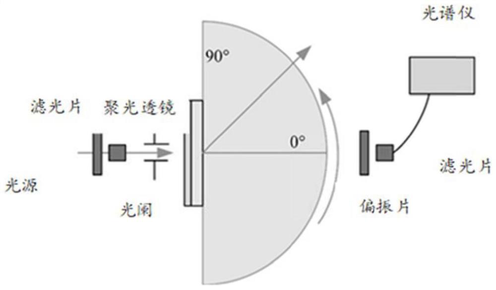
[0092] (1) Coat the luminescent layer material whose base is glass with refractive index matching oil, and fix it on the sample stage of the angle-resolved photoluminescence instrument. Turn on the LED light source (375nm), rotate the turntable 80°, measure the angle-resolved spectral data with a spectrometer through a semi-cylindrical fused silica lens every 1° Use a spectrometer to record spectral data, such as Figure 4 shown.

[0093] (2) At this time, the spectral data obtained at this time is the spectral range of each angle from 0 to 80° and the wavelength from 400nm to 800nm. According to the PL spectrum of the lumi...

Embodiment 2

[0098] This embodiment relates to the molecular orientation of the doped luminescent material RHRD. RHRD is that RD is the luminescent material and RH is the main material. The RD doping ratio is 3% as the luminescent film, the substrate is glass, and it is made by vacuum evaporation. Its area size is about 20mm×20mm. Specifically include the following steps:

[0099] (1) Coat the luminescent layer material whose base is glass with refractive index matching oil, and fix it on the sample stage of the angle-resolved photoluminescence instrument. Turn on the LED light source (375nm), debug and fix it at the 0° position of the rotary table, rotate the rotary table 80°, and use a spectrometer to measure the angle-resolved spectral data through a semi-cylindrical fused silica lens every 1° Use a spectrometer to record spectral data, such as Figure 8 shown.

[0100] (2) At this time, the spectral data obtained at this time is the spectral range of each angle from 0 to 80° and the ...


PUM


Abstract

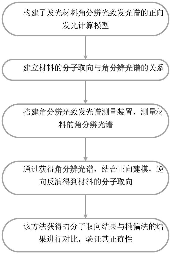
The invention belongs to the related technical field of photoelectric measurement, and discloses a method and device for measuring exciton orientation of a luminescent material, and the method comprises the following steps: (1) constructing a forward luminescence calculation model of the luminescent material for distinguishing a photoluminescence spectrum, utilizing a forward luminescence calculation model to firstly describe quantum mechanics of exciton transition equivalent to classical electromagnetic theoretical description of electric dipole radiation in a microcavity structure, and thenadopting a transmission matrix form based on an electric dipole radiation model and a microcavity coherence model, carrying out transmission and reflection on all involved interfaces by utilizing a Fresnel coefficient to solve an electromagnetic field so as to obtain an emergent spectrum of angular resolution of the luminescent material; and (2) measuring the angular resolution spectrum of the material by adopting a measuring device for exciton orientation of the luminescent material, and performing reverse inversion by combining the forward luminescence calculation model based on the measuredangular resolution spectrum to obtain the molecular orientation of the material. According to the invention, the molecular orientation of the doped material system can be accurately measured and characterized.

Description

technical field [0001] The invention belongs to the technical field of photoelectric measurement, and more specifically relates to a method and device for measuring the exciton orientation of a luminescent material. Background technique [0002] The exciton orientation of the luminescent material determines the physical and optical properties of the film, such as charge mobility, birefringence, ionization potential, etc. Therefore, the photoelectric properties of light-emitting devices are closely related to the exciton orientation of the film layer, such as device lifetime, efficiency, ionization potential and carrier mobility. Therefore, understanding and controlling the exciton orientation of light-emitting materials has always been a very important topic in the research of light-emitting devices. In terms of optics, one of the methods to improve the light coupling efficiency of light-emitting devices is to make the exciton orientation tend to be horizontal. When the ex...

Claims


Application Information

Patent Timeline
Patent Type & Authority Applications(China)
IPC IPC(8): G01N21/63G01N21/21
CPCG01N21/21G01N21/63
Inventor 谷洪刚刘世元王勐田姣姣柯贤华江浩
Owner 武汉宇微光学软件有限公司
Learn More