A high-speed impact welding method, welding system and application
A high-speed impact, welding method technology, applied in welding equipment, non-electric welding equipment, metal processing equipment and other directions, can solve the problems of large-area virtual welding, affecting the overall performance of the weld, and the discontinuity of the weld, achieving a wide range of application prospects, The effect of improving the overall strength and welding quality, and increasing the effective welding area
- Summary
- Abstract
- Description
- Claims
- Application Information
AI Technical Summary
Problems solved by technology
Method used
Image
Examples
Embodiment 1
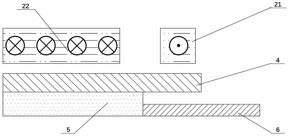
[0063] like image 3 As shown, the present invention proposes a high-speed impact welding system, the load generating device 2 is a flat coil magnet device, which includes a welding section 21 and a circuit section 22 arranged parallel to the flying part 4, and the welding section 21 The cross-sectional area is smaller than the cross-sectional area of the loop section 22; the loop section 22 is used to generate a pulsed magnetic field when the pulse current is passed, and acts on the non-welding area of the flying piece 4 to generate electromagnetic force to drive the flying piece 4 The non-welding area is close to the positioning device 5; the welding section 21 is used to generate a pulsed magnetic field when the pulse current is passed, and acts on the welding area of the flying part 4 to generate electromagnetic force to drive the flying part 4 The welding area moves away from the welding section 21 to achieve welding with the base member 6 .
[0064] Specifically, ...
Embodiment 2
[0066] like Figure 4 As shown, the present invention proposes a high-speed impact welding system, the load generating device 2 is a uniform pressure coil device, including a coil 23 and a conductive channel 24; the conductive channel 24 is placed on the flying part 4 and connected to the The flying part 4 forms a closed circuit; the coil 23 is arranged inside the conductive channel 24 and above the welding area of the flying part 4; the coil 23 is used to generate a pulsed magnetic field when a pulse current is passed; the closed The circuit is used to induce the opposite eddy current under the action of the pulsed magnetic field, and then generate electromagnetic repulsion force to drive the welding area of the flying part 4 to move away from the coil 23 , so as to achieve welding with the base part 6 .
[0067] Specifically, when the coil 23 passes a large pulse current, the conductive channel 24 and the flying part 4 will induce an eddy current in the opposite directio...
Embodiment 3
[0069] like Figure 5 As shown, the present invention proposes a high-speed impact welding system, the load generating device 2 is an energetic explosive device 25; the energetic explosive device 25 is placed above the flying part 4, and it is used to After the pulse current heats up and explodes, a shock wave is generated. The shock wave acts on the welding area of the flying part 4 and drives the flying part 4 to hit the base part 6 to realize welding.
[0070] Specifically, an energetic explosive is placed above the flying piece 4, preferably, the energetic explosive is a wire foil, and the pulse power supply discharges the metal wire foil, so that the temperature of the wire foil is raised instantaneously. Under the condition of high temperature and energization, the metal wire foil gasifies and reacts with the liquid in the welding chamber to produce a large amount of hydrogen gas, which causes an explosion. The high-pressure gas increases the pressure in the welding c...
PUM
 Abstract
Description
Claims
Application Information
 - Generate Ideas
- Intellectual Property
- Life Sciences
- Materials
- Tech Scout
- Unparalleled Data Quality
- Higher Quality Content
- 60% Fewer Hallucinations
Browse by: Latest US Patents, China's latest patents, Technical Efficacy Thesaurus, Application Domain, Technology Topic, Popular Technical Reports.
© 2025 PatSnap. All rights reserved.Legal|Privacy policy|Modern Slavery Act Transparency Statement|Sitemap|About US| Contact US: help@patsnap.com


