
A cnc strengthened milling lathe

A reinforced, milling technology, applied in turning equipment, metal processing equipment, metal processing machinery parts, etc., can solve the problems of inconvenient operation, reduce user work efficiency, waste falling, etc., and achieve extended service life, The effect of improving stability and improving efficiency

Active Publication Date: 2021-10-12
惠州市创锋科技有限公司
View PDF1 Cites 0 Cited by
  • Summary
  • Abstract
  • Description
  • Claims
  • Application Information

AI Technical Summary

Problems solved by technology

[0004] In the process of realizing the present invention, it is found that there are at least the following problems in the prior art that have not been solved: 1. When the milling lathe is milling workpieces, often a large amount of waste chips will fall in the groove, and generally a high-pressure air pump is used to connect the nozzle , the nozzle sprays gas to blow the waste out of the groove, the waste is not convenient for the user to clean and collect, and reduces the user's work efficiency;
[0005] 2. After cleaning the groove, the user needs to wipe the groove and the table, which takes a lot of time and is not convenient for the user to operate;

Method used


Image

  • A cnc strengthened milling lathe
  • A cnc strengthened milling lathe
  • A cnc strengthened milling lathe

Examples


Embodiment Construction

[0039] The technical solutions of the present invention will be clearly and completely described below in conjunction with the embodiments. Obviously, the described embodiments are part of the embodiments of the present invention, but not all of them. Based on the embodiments of the present invention, all other embodiments obtained by persons of ordinary skill in the art without making creative efforts belong to the protection scope of the present invention.

[0040] In describing the present invention, it is to be understood that the terms "center", "longitudinal", "transverse", "length", "width", "thickness", "upper", "lower", "front", " Back", "Left", "Right", "Vertical", "Horizontal", "Top", "Bottom", "Inner", "Outer", "Clockwise", "Counterclockwise", etc. or The positional relationship is based on the orientation or positional relationship shown in the drawings, which is only for the convenience of describing the present invention and simplifying the description, rather t...


PUM


Abstract

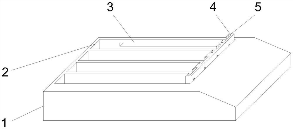
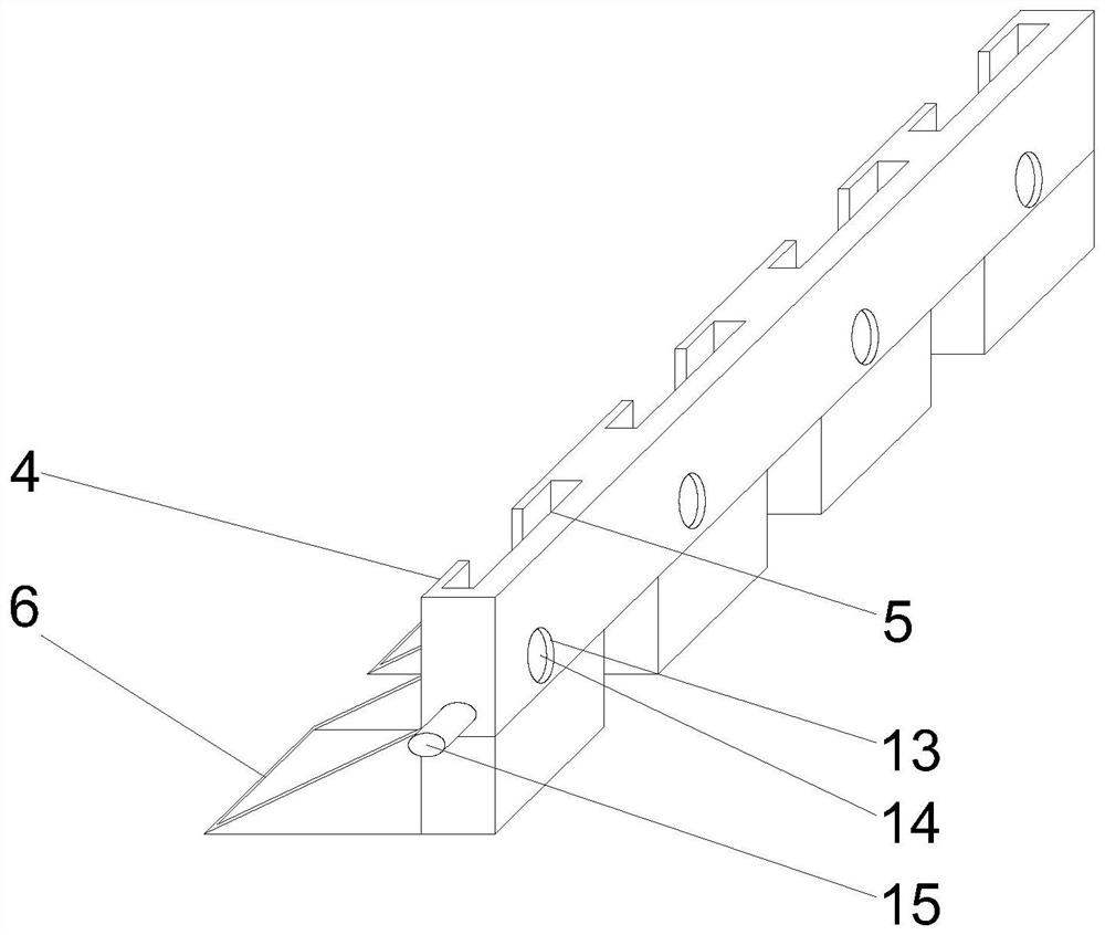
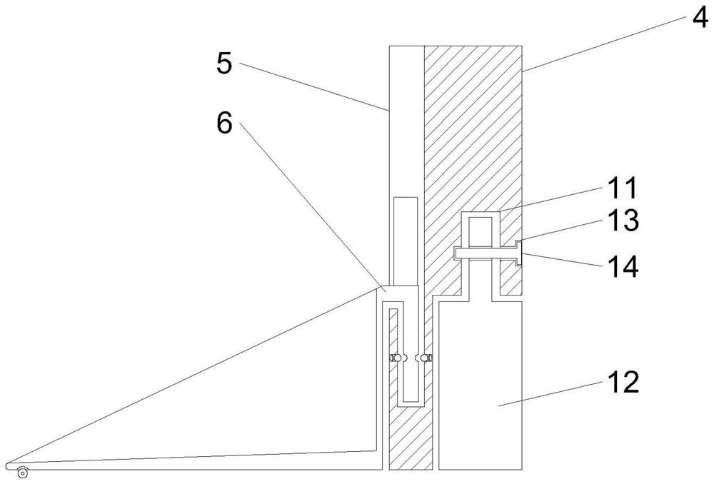
The invention provides a CNC reinforced milling lathe, comprising a workpiece resting platform, a rectangular groove is opened on the outer surface of the upper end of the workpiece resting platform, and a scraper is slidably connected to the inside of the rectangular groove, and the outer surface of the upper end of the scraper is There is a movable groove on the surface, a collection groove is arranged inside the movable groove, a connecting groove is arranged on the outer surface of the lower end of the scraper, cleaning cotton is inserted into the connecting groove, and a collection groove is arranged on the inner surface of the movable groove. There is an arc-shaped groove, and a spring washer is arranged inside the arc-shaped groove, and a block is arranged inside the arc-shaped groove. The scraps inside are cleaned and collected in a centralized manner. When the user cleans up the scraps in the workpiece rest table and the rectangular slot, the rectangular slot can be wiped and re-oiled, thereby improving the user's work efficiency and reducing the user's operation steps.

Description

technical field [0001] The invention relates to the technical field of milling lathes, in particular to a CNC reinforced milling lathe. Background technique [0002] A lathe is a machine tool that mainly uses a turning tool to turn a rotating workpiece. The lathe is mainly used to process shafts, discs, sleeves and other workpieces with rotating surfaces. It is the most widely used type of machine tool in machinery manufacturing and repair factories. Some lathes are generally used to process rotary parts. The parts are clamped on the main shaft of the machine tool through the three-grip chuck and rotated at a high speed. It can process the inner hole, thread, bite, etc. [0003] Existing patent (notification number: CN208543263U) a lathe capable of milling, its structure includes a milling tool holder, a workpiece rest table, a shock absorber, a controller, a knob, a power cord, a connecting column, a rubber block, a base, a bracket, Power box, connection disc, driver, fix...

Claims


Application Information

Patent Timeline
Patent Type & Authority Patents(China)
IPC IPC(8): B23B25/00B23Q11/10B23Q11/00
CPCB23B25/00B23Q11/0042B23Q11/1069
Inventor 曹瑞王乐
Owner 惠州市创锋科技有限公司
Learn More