Vandal proof electronic memory card reader

A technology of electronic storage and reader, applied in the field of electronic storage card reader

Inactive Publication Date: 2003-09-17
SCHLUMBERGER IND INC
View PDF1 Cites 0 Cited by
  • Summary
  • Abstract
  • Description
  • Claims
  • Application Information

AI Technical Summary

Problems solved by technology

In both cases, the user who arrives after the malicious act has been carried out cannot use the reader because the part that constitutes the main body of the card known as a "counterfeit card" cannot be extracted from the guide slot
This requires the intervention of a maintenance crew and the outage of the reader for a considerable period of time

Method used


Image

  • Vandal proof electronic memory card reader
  • Vandal proof electronic memory card reader
  • Vandal proof electronic memory card reader

Examples


Embodiment Construction

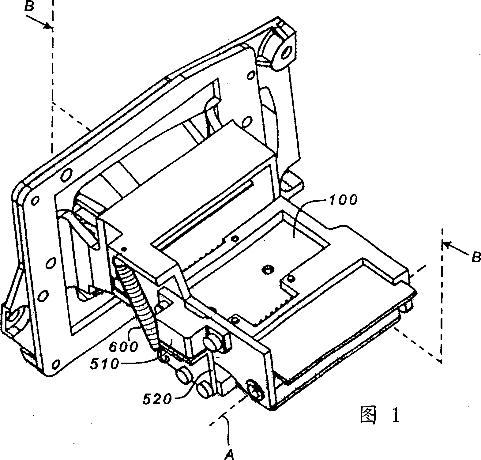
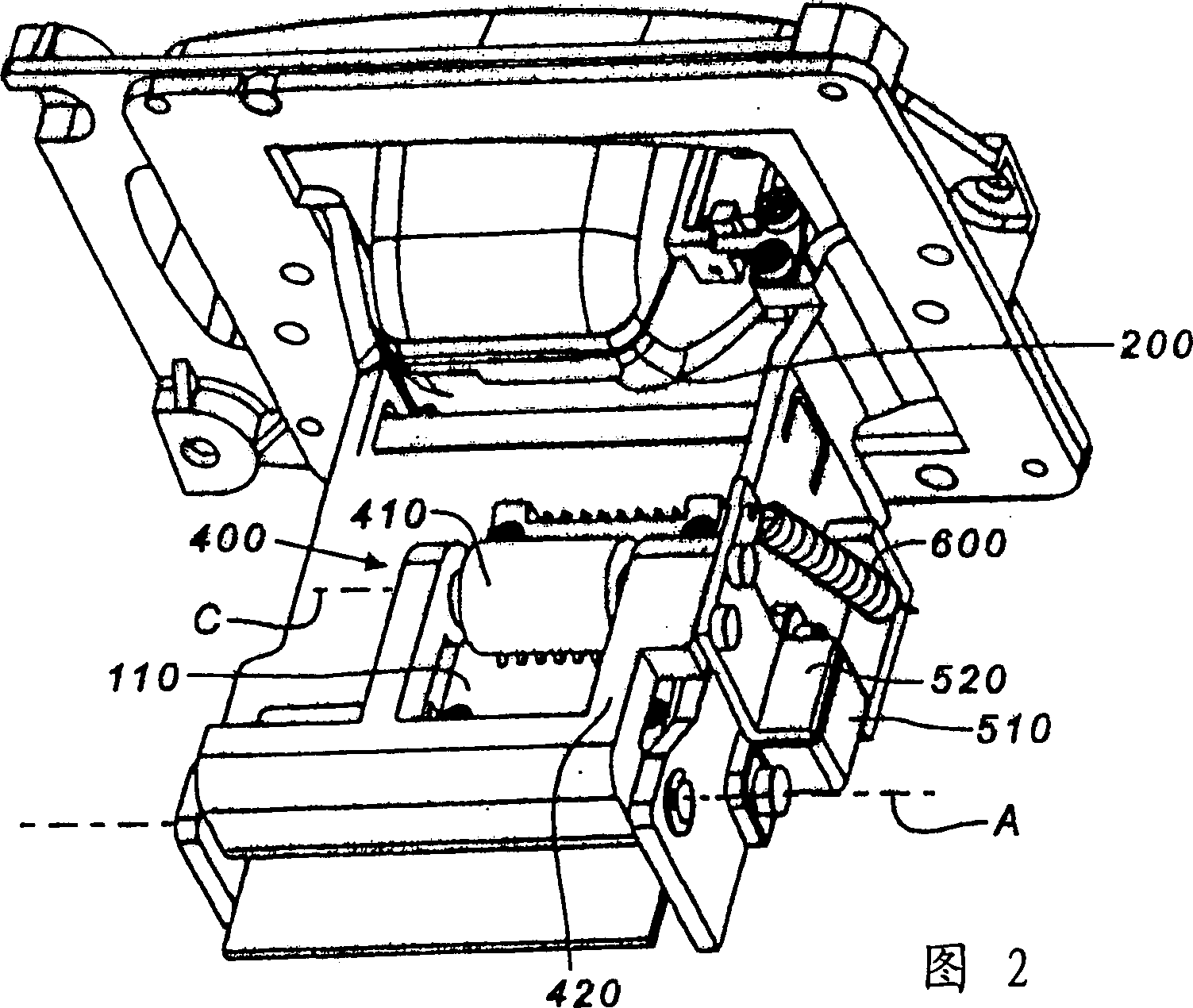
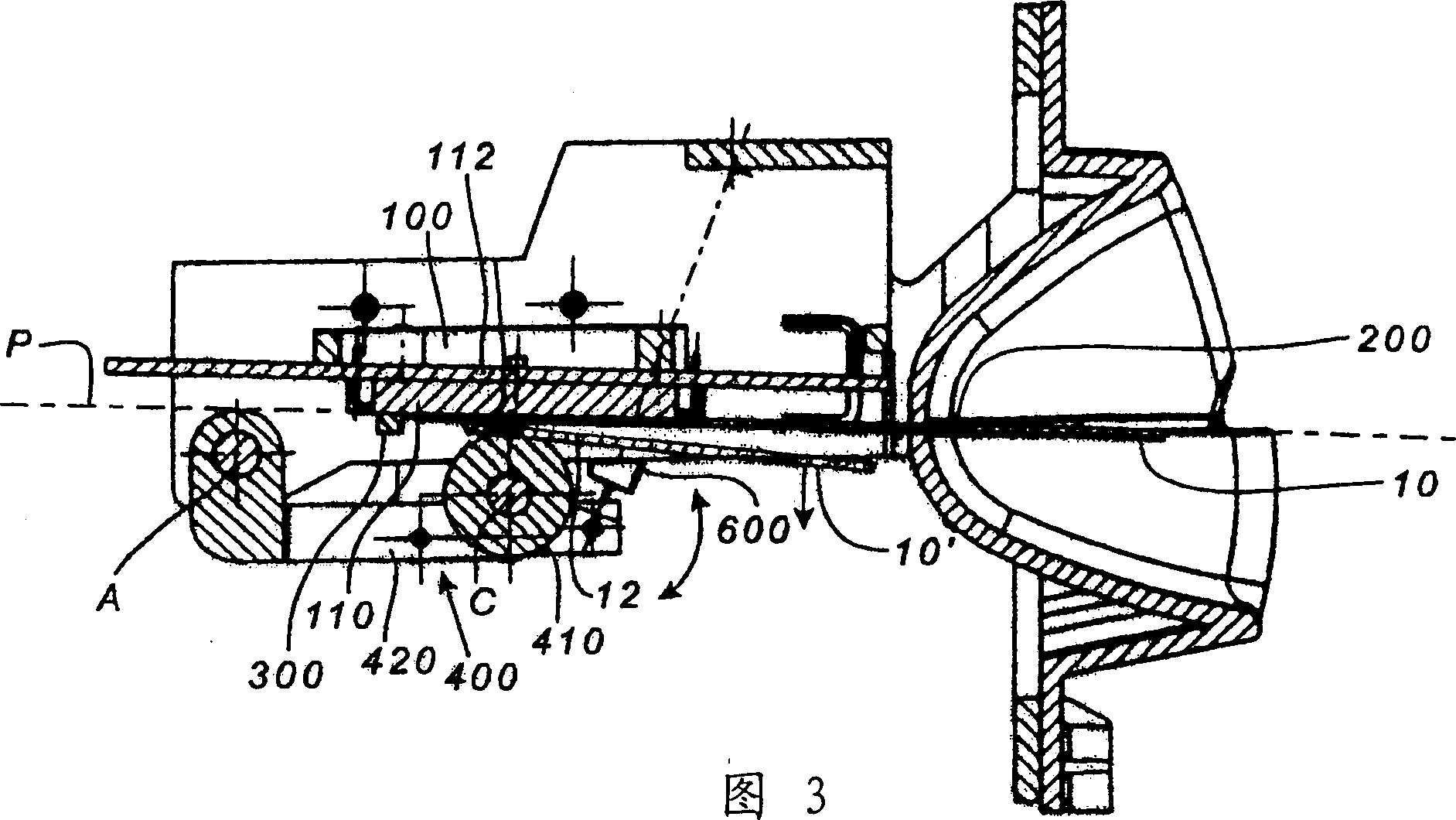
[0023] Figures 1, 2 and 3 illustrate a card reader designed to read and / or write data on an electronic memory card, such as a telephone card of a public telephone. As shown in FIG. 5 , the electronic memory card 10 includes a card body 11 made of plastic, and contact areas 12 arranged on one side of the card body 11 . Each contact area 12 is electrically connected to an integrated circuit or chip, which is embedded in the card body 11 and contains at least one memory circuit.

[0024] The reader itself comprises a reading head 100 with the function of exchanging data with the memory circuit of the card 10 in the reading and / or writing mode. For this purpose, the read head 100 comprises a connector 110 with connecting parts 112 designed to make electrical contact with the contact areas 12 of the card 10 . exist Figure 4 It is pointed out that the connector 110 of the read head 100 includes two groups of 8 connectors 112 each, so that, provided that the contact areas 12 can be...


PUM


Abstract

An electronic memory card reader (10) for reading a card comprising a card body (11) and electrical contact areas (12). The reader includes a read head (100) having connection elements (112) designed to cooperate with the contact areas (12), an insertion slot (200), an abutment (300) for the card body, defining a processing position in which the areas (12) are in contact with the connection elements (112), and a moving part (400) that is rotatable, and that is capable, firstly, in a closed position, of establishing electrical contact between the elements (112) and the areas (12) in the processing position and, secondly, of moving away from the closed position under the action of a force developed by the card (10) moving in translation. The part (400) is returned to the closed position by resilient return means (600).

Description

technical field [0001] The invention relates to an electronic memory card reader. Background technique [0002] In the following description, "reader" refers to a device capable of not only reading, but possibly also writing data into the memory on said electronic memory card. [0003] Electronic memory cards are widely known today. The card basically consists of a generally rectangular card body in which an electronic module is housed. The electronic module is an integrated circuit comprising at least one memory circuit and electrical contact areas arranged on one side of the card body and connected to terminals of the integrated circuit. In order to use such a card, the card is inserted into a processor. The processor includes processing circuits to utilize the data contained in the memory of the card and correct said data, and a reader so that a temporary electrical connection can be established between the contact areas of the card and the processing circuits of the m...

Claims


Application Information

Patent Timeline
IPC IPC(8): G06K7/00
CPCG06K7/0021G06K7/003
Inventor 阿兰·伯纳德
Owner SCHLUMBERGER IND INC
Why Eureka
Try Eureka