Methods and Systems for Decoding Polar Codes

a technology of polar codes and methods, applied in the field of polar codes, can solve the problems of data compression either lossless or lossy, incorrect data being received through decision-making processes at the receiver, and information loss, and achieve the effect of improving the performance of decoders

Active Publication Date: 2013-05-09
THE ROYAL INSTITUTION FOR THE ADVANCEMENT OF TECH MCGILL UNIV +1
View PDF1 Cites 245 Cited by
  • Summary
  • Abstract
  • Description
  • Claims
  • Application Information

AI Technical Summary

Benefits of technology

[0012]It is an object of the present invention to mitigate drawbacks within the prior art relating to polar codes and more specifically to implementing and improving the performance of decoders for polar codes.

Problems solved by technology

With respect to data compression this can be either lossless or lossy.
On the one hand this is due to necessity as most physical phenomena are real valued and storing them in digital form must involve some form of quantization, and hence, some loss of information.
However, if the redundancy is added through coding then it is possible to reconstruct the original data at the receiver in the presence of noise, which results in incorrect data being received through decision making processes at the receiver.
However, adding this redundancy comes at the cost of reducing the effective rate of data transmission for a given data transmission rate as in addition to the data we must also transmit the redundant data.
However, designing capacity-achieving codes with an explicit construction eluded researchers until Ankan proposed polar codes, see E. Ankan, “Channel Polarization: A Method for Constructing Capacity-Achieving Codes for Symmetric Binary-Input Memoryless Channels” (IEEE Trans. on Inf.
This presents a real challenge when it comes to implementing the decoders, for example successive cancellation (SC) decoders, in hardware.

Method used


Image

  • Methods and Systems for Decoding Polar Codes
  • Methods and Systems for Decoding Polar Codes
  • Methods and Systems for Decoding Polar Codes

Examples


Embodiment Construction

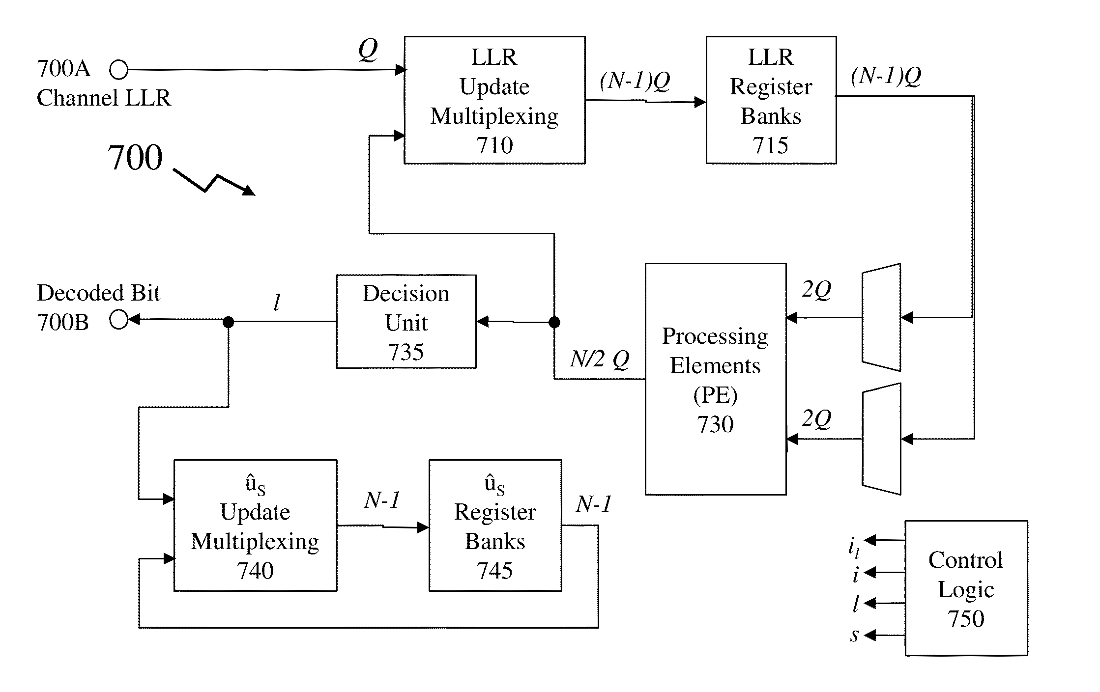
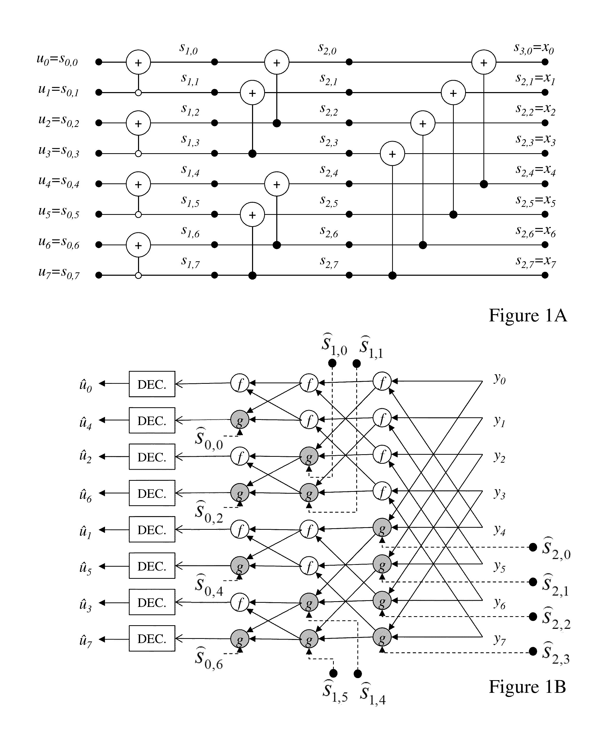
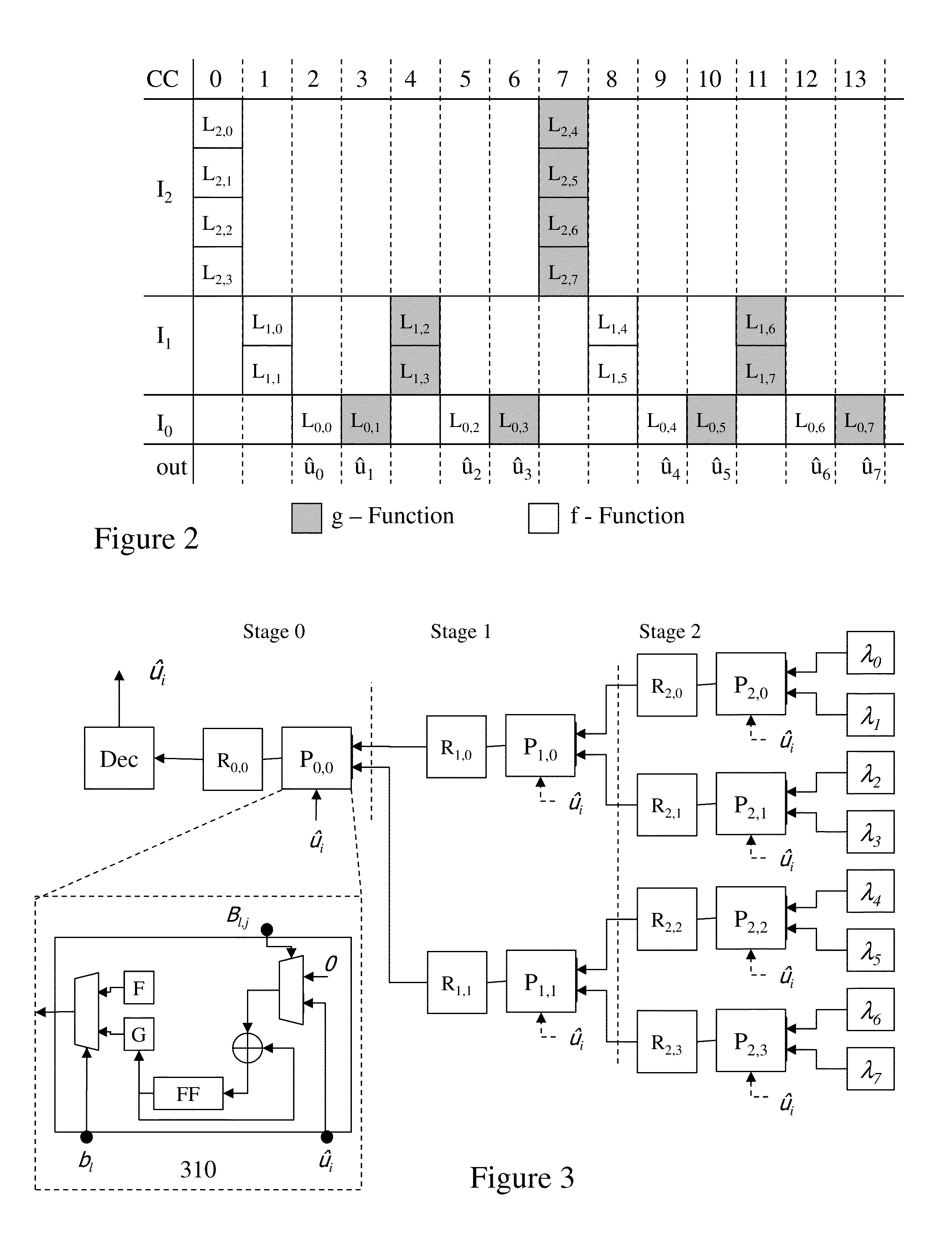
[0060]The present invention is directed to polar codes and more specifically to implementing and improving the performance of decoders for polar codes.

[0061]The ensuing description provides exemplary embodiment(s) only, and is not intended to limit the scope, applicability or configuration of the disclosure. Rather, the ensuing description of the exemplary embodiment(s) will provide those skilled in the art with an enabling description for implementing an exemplary embodiment. It being understood that various changes may be made in the function and arrangement of elements without departing from the spirit and scope as set forth in the appended claims.

[0062]1: Polar Codes

[0063]A polar code is a linear block error-correcting code designed for a specific discrete-input, memoryless channel. Such codes may be used in forward error correction (FEC) and applied to transmitting data on a communications channel such that errors in the communication can be corrected and / or detected by the rec...


PUM


Abstract

Coding within noisy communications channels is essential but a theoretical maximum rate defines the rate at which information can be reliably transmitted on this noisy channel. Capacity-achieving codes with an explicit construction eluded researchers until polar codes were proposed. However, whilst asymptotically reaching channel capacity these require increasing code lengths, and hence increasingly complex hardware implementations. It would be beneficial to address architectures and decoding processes to reduce polar code decoder complexity both in terms of the number of processing elements required, but also the number of memory elements and the number of steps required to decode a codeword. Beneficially architectures and design methodologies established by the inventors address such issues whilst reducing overall complexity as well as providing methodologies for adjusting decoder design based upon requirements including, but not limited to, cost (e.g. through die area) and speed (e.g. through latency, number of cycles, number of elements etc).

Description

CROSS-REFERENCE TO RELATED APPLICATIONS[0001]This application claims the benefit of priority from U.S. Provisional Patent Application Ser. No. 61 / 556,862 filed Nov. 8, 2011 entitled “Method and Device for the Decoding of Polar Codes” and U.S. Provisional Patent Application Ser. No. 61 / 639,150 filed Apr. 27, 2012 entitled “Semi-Parallel Architecture for Successive Cancellation Decoding of Polar Codes.”FIELD OF THE INVENTION[0002]The present invention relates to polar codes and more specifically to implementing and improving the performance of decoders for polar codes.BACKGROUND OF THE INVENTION[0003]Two recurring central topics in information theory are efficient compression and reliable transmission of data. In the fast 20 years or so communications and information technologies have fundamentally changed how we access information, interact as a society, and communicate. Today, these central topics are everywhere in our daily lives whether they arise in our use of portable electronic...

Claims


Application Information

Patent Timeline
Patent Type & Authority Applications(United States)
IPC IPC(8): G06F17/10
CPCG06F17/10H03M13/13H03M13/1191H03M13/1111H03M13/6561H03M13/6563H03M13/6577G06F16/9024G06F16/9027G06F17/142G06F17/16H03M13/157H03M13/1575H03M13/3927H03M13/617
Inventor GROSS, WARRENSARKIS, GABIRAYMOND, ALEXANDRELEROUX, CAMILLETAL, IDOVARDY, ALEXANDER
Owner THE ROYAL INSTITUTION FOR THE ADVANCEMENT OF TECH MCGILL UNIV
Why Eureka
Try Eureka