
Twisting device of composite yarn for spinning

A twisting device and yarn technology, applied in spinning machines, textiles and papermaking, continuous winding spinning machines, etc., can solve the problems of inability to install the yarn bobbin, the yarn bobbin is pulled out, and the yarn is not taut.

Inactive Publication Date: 2021-01-01
绍兴柯桥富荣纺织有限公司
View PDF14 Cites 2 Cited by
  • Summary
  • Abstract
  • Description
  • Claims
  • Application Information

AI Technical Summary

Problems solved by technology

[0003] Although the existing twisting machine can twist the yarn, it often encounters the following problems: 1. When many yarns are transported to the twisting area, it is inevitable that a small amount of yarn will be in the undeveloped position during the transport process. The tight situation will easily lead to partial relaxation of the strands after twisting, which will have a certain impact on the twisting process
2. There are a lot of hairiness attached to the yarn unwound from the yarn bobbin. If twisted into strands, this will undoubtedly affect the appearance, feel and performance of the strands
3. The yarn bobbin is directly set on the yarn frame. When the yarn disk rotates, the yarn disk drives the yarn frame to make a circular motion, thereby driving the yarn bobbin to make a circular motion. When the speed of the yarn disk is too fast , it is easy to cause the yarn bobbin to come out of the yarn frame, and then the twisting cannot be performed normally
4. Since the height of the yarn rack is always the same, only yarn bobbins with the same height can be installed on it, but yarn bobbins with different heights cannot be installed, and there are limitations in use

Method used

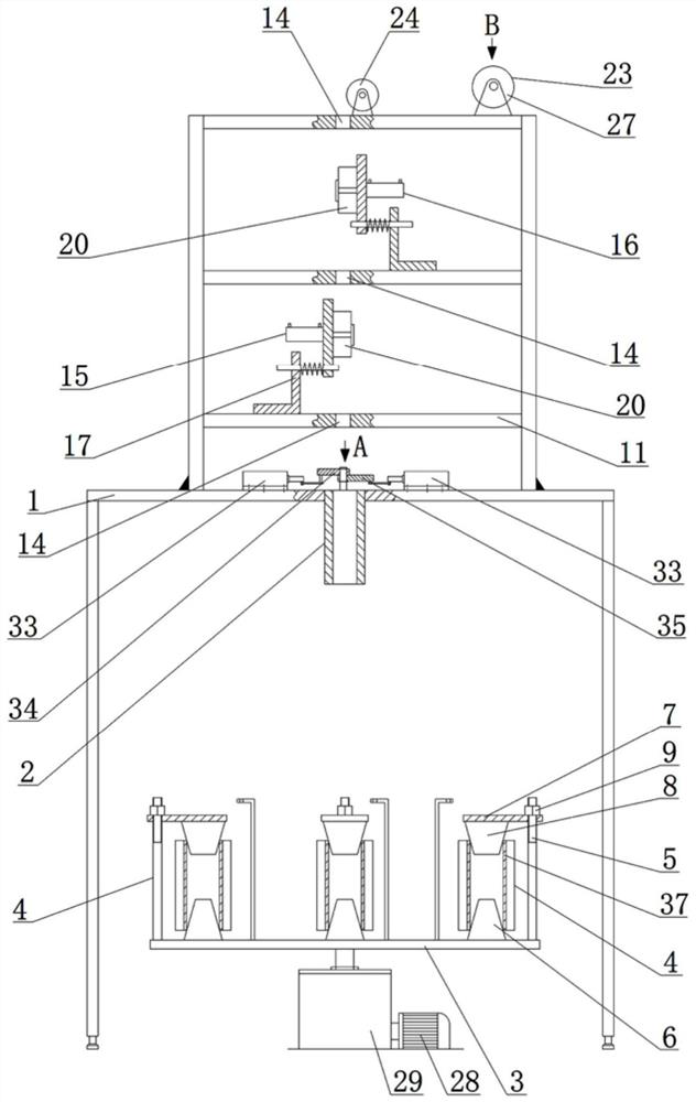
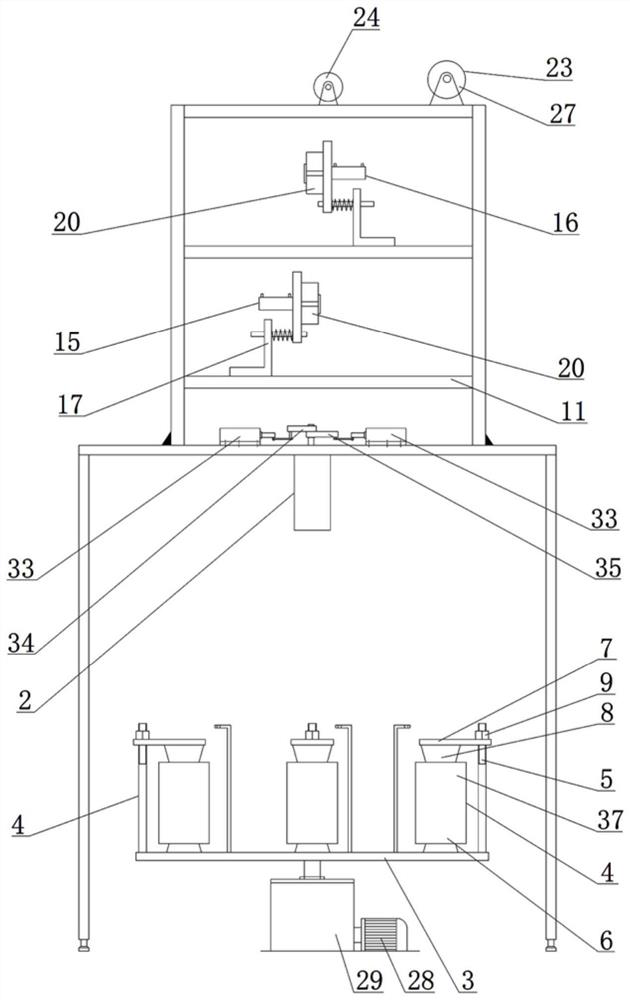
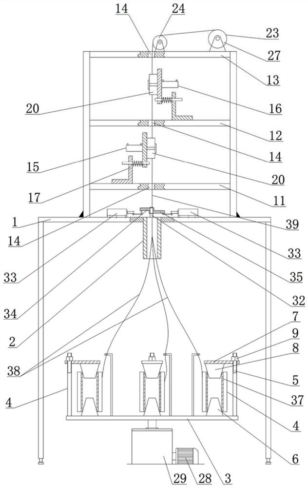

Image

  • Twisting device of composite yarn for spinning
  • Twisting device of composite yarn for spinning
  • Twisting device of composite yarn for spinning

Examples


Embodiment Construction

[0034]The present invention will be further described below in conjunction with the accompanying drawings. The protection scope of the present invention is not limited to the following:

[0035]Such asFigure 1~8As shown in Figure 10, a twisting device for composite yarns for textiles includes a gantry 1, and a polymer tube 2 is fixed on the beam of the gantry 1, and the polymer tube 2 is arranged through the beam. A power unit is arranged below the beam, and the output shaft of the power unit is arranged upwards. The output shaft of the power unit is welded with a twisting disc 3. The power unit includes a motor B28 and a reducer 29. The motor B28 and the gantry 1 are both supported on the ground Above, the output shaft of the motor B28 and the input shaft of the reducer 29 are connected via a coupling, the twisting disc 3 is installed on the output shaft of the reducer 29, and the twisting disc 3 is on the top surface and along its circumference. A plurality of yarn drum mounting unit...


PUM


Abstract

The invention discloses a twisting device of composite yarn for spinning. The twisting device comprises a portal frame, a polymerization pipe is fixedly arranged on a cross beam of the portal frame, apower unit is arranged below the cross beam of the portal frame, an output shaft of the power unit is arranged upwards, and a twisting disc is welded to the output shaft of the power unit; a plurality of yarn bobbin mounting units are arranged on the top surface of the twisting disc in the circumferential direction of the twisting disc, each yarn bobbin mounting unit comprises a threaded rod anda lower conical barrel which are fixedly arranged on the twisting disc, an upper conical barrel extends into an upper port of a yarn bobbin, the threaded section of each threaded rod is in threaded connection with a nut, and each nut abuts against the top of a corresponding cover plate; and a hairiness removing device A and a hairiness removing device B are arranged on a lower partition plate anda middle partition plate respectively, and a rubber block is fixedly arranged on the right end face of a movable plate. The device has the beneficial effects that the structure is compact, yarn bobbins with different heights can be installed, prepared plied yarn is prevented from loosening, hairiness can be efficiently removed, and operation is easy.

Description

Technical field[0001]The invention relates to the technical field of textile processing, in particular to a twisting device for a composite yarn for textile.Background technique[0002]When using cotton yarn to spin into cotton fabric, the yarn needs to be twisted. Twisting is to twist two or more single yarns into strands, so as to obtain better quality conditions such as molding and strength. If the yarn is not twisted, it will cause two or more single yarns to have no cohesion after being twisted together, and they will be separated by external forces, which will ultimately affect the quality of the strands. The existing twisting machine works by fixing one end of two or more single yarns, and then rotating the other end of the single yarn multiple times in the same direction, thereby twisting to obtain a strand.[0003]Although the existing twisting machine can twist the yarn, it often encounters the following problems: 1. When multiple yarns are transported to the twisting zone, it...

Claims


Application Information

Patent Timeline
IPC IPC(8): D01H1/10D01H1/16D01H1/26D01H13/10D01H13/30
CPCD01H1/103D01H1/16D01H1/26D01H13/10D01H13/308
Inventor 冯小军李凤
Owner 绍兴柯桥富荣纺织有限公司
Learn More