Eureka AIR delivers breakthrough ideas for toughest innovation challenges, trusted by R&D personnel around the world.

Buoyancy-adjustable device and method for auxiliary installation of underwater equipment

A technology for underwater equipment and installation devices, which is applied in the direction of underwater operation equipment, transportation and packaging, ships, etc., which can solve the problems of large bearing capacity of installation cables and inconvenient transportation of underwater equipment, and achieve the effect of precise installation

Inactive Publication Date: 2014-04-30
CHINA UNIV OF PETROLEUM (EAST CHINA) +1
View PDF5 Cites 22 Cited by
  • Summary
  • Abstract
  • Description
  • Claims
  • Application Information

AI Technical Summary

Problems solved by technology

[0003] In order to overcome the defects of the prior art, the present invention provides a buoyancy-adjustable auxiliary installation device and installation method for underwater equipment, which offsets the buoyancy of the underwater equipment by adding a buoyancy-adjustable floating body device during the installation process of the underwater equipment. The device can realize the wet towing transportation and non-floating weight installation of underwater equipment, so as to solve the problems of conventional underwater equipment installation technology, such as inconvenient transportation of underwater equipment and excessive bearing capacity of installation cables.

Method used


Image

  • Buoyancy-adjustable device and method for auxiliary installation of underwater equipment
  • Buoyancy-adjustable device and method for auxiliary installation of underwater equipment
  • Buoyancy-adjustable device and method for auxiliary installation of underwater equipment

Examples


Embodiment Construction

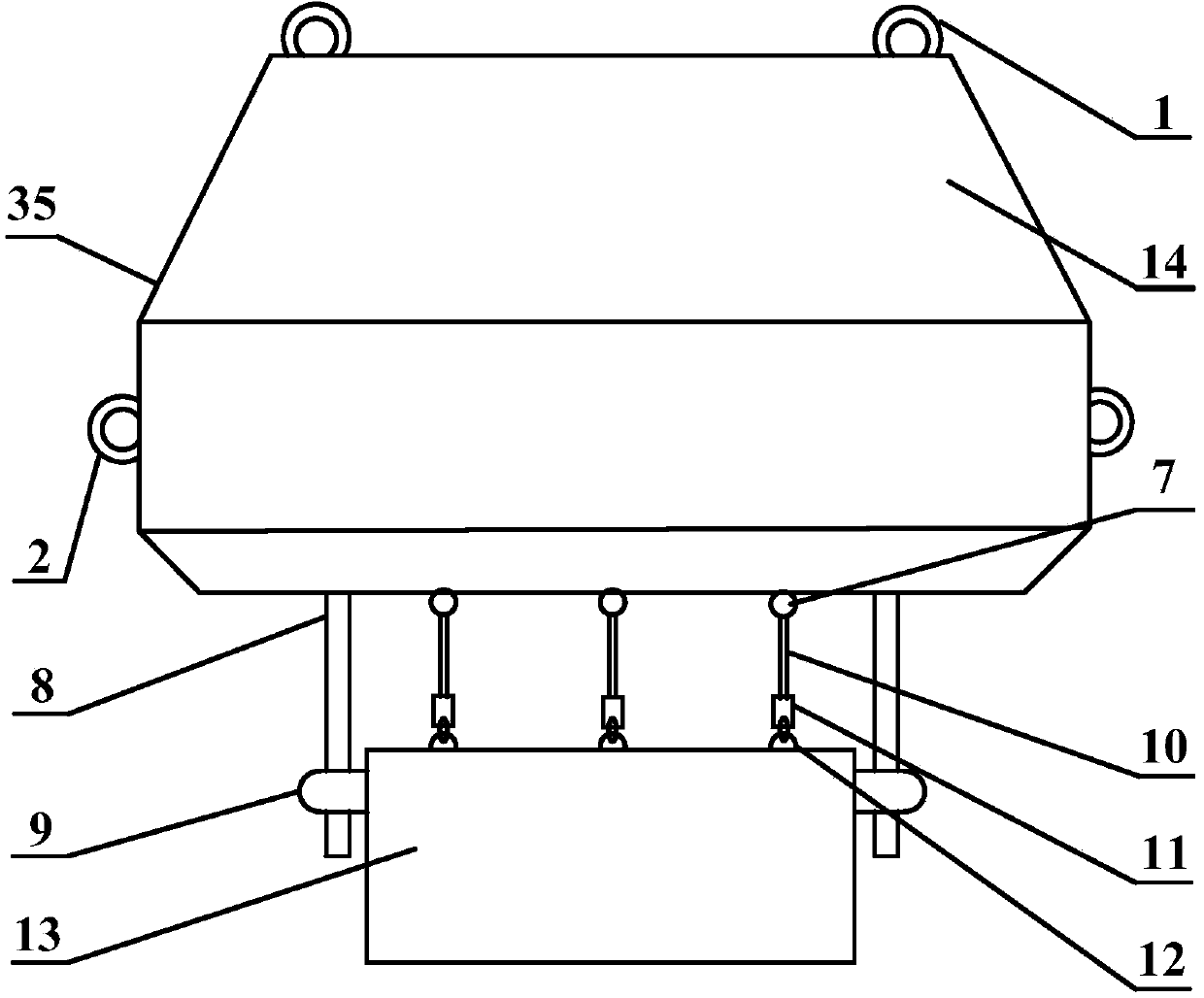
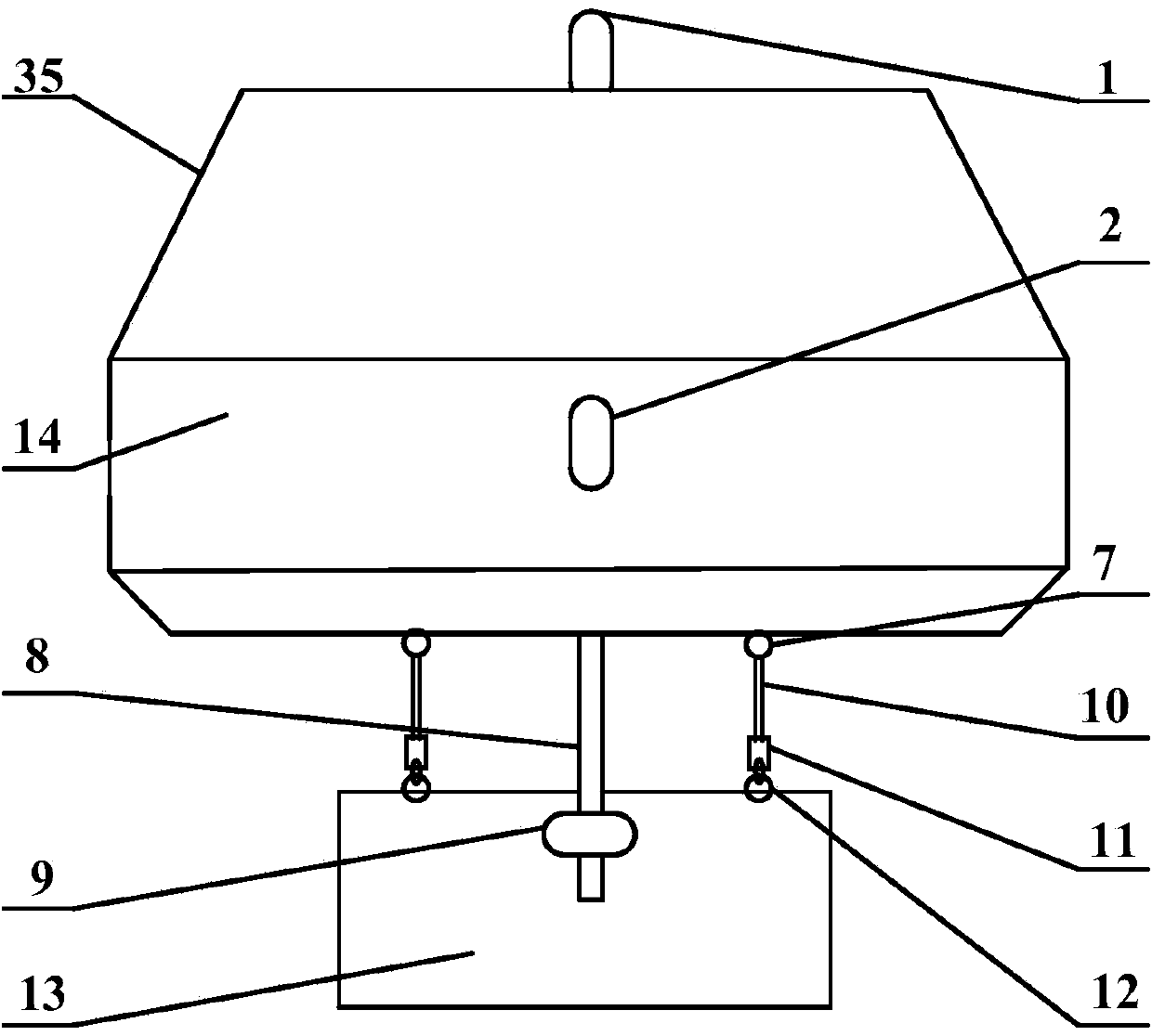
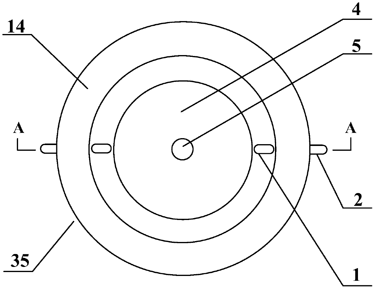
[0029] Such as figure 1 , figure 2 , image 3 , Figure 4 As shown, the buoyancy-adjustable underwater auxiliary installation device includes: a buoyant body 14 , a top lug 1 , a side lug 2 , a bottom lug 7 , a suspension cable 10 , a positioning rod 8 , and a hydraulic shackle 11 .

[0030] The main body of the floating body 14 is a cylinder, and the upper end and the lower end form a conical surface; the floating body 14 is made of solid buoyancy material, which has strong pressure resistance; the solid buoyancy material can be chemical foam composite material, microsphere foam composite material or light synthetic Buoyancy materials such as composite materials.

[0031] The floating body 14 is provided with a funnel-shaped inlet cone 4, a cylindrical inlet hole 5, and a gyro-shaped weight cabin 6 in sequence from top to bottom in the axial direction, and the funnel-shaped inlet cone 4 and the gyro-shaped weight cabin 6 are connected through the cylindrical inlet hole 5 ...


PUM


Abstract

The invention belongs to the field of marine engineering and particularly relates to a buoyancy-adjustable device and a method for auxiliary installation of underwater equipment. The buoyancy-adjustable device for auxiliary installation of underwater equipment comprises a buoy, a top lifting lug, a side lifting lug, a bottom lifting lug, a lifting cable, a locating rod and a hydraulic shackle, wherein the main body of the buoy is cylindrical, and conic surfaces are formed at the upper end and the lower end of the buoy; the buoy is made of a solid buoyancy material; the top lifting lug, the side lifting lug and the bottom lifting lug are arranged at the top of the buoy; a funnel-shaped guide-in cone, a cylindrical guide-in hole and a gyro-shaped balance weight cabin are sequentially arranged in the axial direction of the buoy from the top to bottom, the funnel-shaped guide-in cone and the gyro-shaped balance weight cabin are communicated through the cylindrical guide-in hole, three oblique water ducts which are communicated with the exterior are arranged at the bottom of the balance weight cabin, and the three water ducts are uniformly distributed in the circumference direction. Small pull force is applied on an installation rope in the installation process, and the buoyancy material which is used as the material of main body of the auxiliary installation device can endure deep water pressure and is suitable for deep water installation.

Description

technical field [0001] The invention belongs to the field of marine engineering, and in particular relates to a buoyancy-adjustable auxiliary installation device and installation method for underwater equipment. Background technique [0002] Underwater equipment installation technology occupies a basic position in marine engineering. At present, the conventional underwater equipment installation technology directly connects underwater equipment through installation rods or installation cables during the installation process. With the increase in the weight of underwater equipment, the installation water depth develops from shallow water to deep water, and the installation cables are often due to unbearable Failure occurs due to excessive tension. In addition, underwater equipment occupies a large area. Conventional underwater installation technology requires a large-area deck transport ship to transport underwater equipment. Hiring such ships is expensive. At present, my co...

Claims


Application Information

Patent Timeline
Patent Type & Authority Applications(China)
IPC IPC(8): B63C11/52
Inventor 曹宇光张士华徐松森初新杰孙晓瑜崔希君王宏安胡雪扬聂文俊周真楷
Owner CHINA UNIV OF PETROLEUM (EAST CHINA)
Why Eureka
Eureka Blog
Learn More